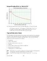
Imager Reading Error vs Source D:S
The following example uses the above Typical Reading Error vs. Source D/S graph:
A 5" diameter source (Size = 5) at a Distance of 50" has D/S = 50/5 = 10.
According to the above graph the imager would read less than 1% low in
temperature (as shown by the dashed line) for this size target.
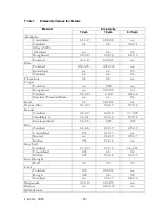
Typical Emissivity Values
The following tables provide references for estimating emissivity and can be used when the
user does not have the means or the time to determine the emissivity value experimentally.
Emissivity values shown in the tables are only approximate. Any or all of the following
parameters can affect the emissivity of an object:
1. Temperature
2. Angle of measurement
3. Geometry (plane, concave, convex, etc.)
4. Thickness
5. Surface quality (polished, rough, oxidized, sandblasted)
6. Spectral region of measurement
7. Transmissivity (i.e., thin film plastics)
Note
1:
These tables are to be used as a guide only, as emissivity changes with temperature,
viewing angle, wavelength, target geometry and surface finish.
Note
2:
Your Ti30 thermal imager measures infrared energy in the 7 – 14 µm range.
Jan 31st, 2005
- 88 -
Summary of Contents for Ti30
Page 4: ...Appendix B Infrared Theory Q A 92 Glossary 96 Jan 31st 2005 4 ...
Page 25: ...Man Machine Interface Flow Charts Main Loop Jan 31st 2005 25 ...
Page 26: ...Image Recording Procedure Emissivity Adjustment Procedure Jan 31st 2005 26 ...
Page 70: ...Jan 31st 2005 70 ...
Page 86: ...Jan 31st 2005 86 ...

