background image

2-29

VIBXPER

T II Balancing 12.2019

Measurement setup

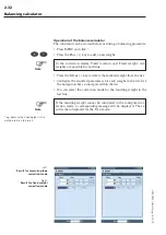
In order to edit or create a measurement setup proceed as follows:
•  Mark a rotor type in the selection screen (see p. 2-11).
•  Press the MENU button and click on "Task manager".
•  Select a user-defined task.
•  Mark the "Measurement setup" field.
•  Press the MENU button and click on "New" or on "Edit":

The following parameters can be edited:

f

ilter

0.5 / 1 / 2 / 10 Hz

; select "10 Hz" as the lowest frequency if the 

machine RPM is more than 600 RPM and the machine is placed on 

a soft foundation.

l

owpass


filter

Yes / No

; To suppress high frequency noise signals, a 

low pass filter (1 kHz) can be activated (Yes). With 'No', the signal 

is processed without the low pass filter.

n

o

of


MeasureMents

1 - 20

; the number of measurements is auto-

matically increased to the maximum value if the indicator shows 

strongly varying imbalance.

t

iMe


synchronous


aVeraging

:

 In this type of averaging, the time signals of 

each individual rotation are averaged to reduce non-synchronous 

components in the signal. The calculated phase values are likewise 

averaged to increase the stability of the phase vector. The param-

eters for the phase averaging correspond to the settings under "No 

of measurements' (see above). The number of time synchronous 

averages is either RPM-dependent, user-defined or infinite:

  ‘Auto’: Time synchronous number of averages is rpm-dependent.

  ‘Manual’: Time synchronous number of averages can be entered 

(max. 254).

  ‘Infinite’: Each individual measurement is averaged with the pre-

ceding individual measurement. The longer the measurement 

takes, the more stabile the final 

result. This average type is gen-

erally used for balancing. The 

measurement must be stopped 

using the Enter key.

M

easureMent


range

:

 The measure-

ment range for the analog chan-

nel (A/B) can be automatically 

matched to the input signal 

('Auto') or set to fixed. When set 

to ‘[Value] / Auto-Up’, the mea-

surement range is automatically 

increased when the upper limit 

is exceeded.

Measurement setup

Parameters in the 
measurement setup 

Summary of Contents for VIBXPERT II

Page 1: ...VIBXPERT II Operating Instructions Balancing ...

Page 2: ...cing Operating Instructions VIBXPERT II Dual channel FFT data collector and signal analyzer Edition December 2019 Order no LIT 53 202 EN Translation of the german manual Series VIB 5 310 Firmware version 3 2x ...

Page 3: ...ermore under no circumstances may the publisher be held liable for direct or in direct damage of any kind resulting from use of the product or the manual even if the publisher has expressly indicated the potential for occurrence of such damage The publisher assumes no liability for any product defects This warranty and liability limitation applies to all distributors and sales partners as well Tra...

Page 4: ... not wish to attach a balancing weight to the rotor VIBXPERT will calculate the mass that should be milled from the rotor And just think VIBXPERT even grows to meet your future require ments The latest analysis and diagnostic functions are added on a regular basis and made available as an update This ensures that you are always have the most modern equipment For further information visit us on the...

Page 5: ...16 Trim run 2 16 Saving the result 2 16 Evaluation of the data 2 17 Options for balancing 2 18 1 Combining balancing weights 2 18 2 Changing the correction mode Tools menu Machine setup 2 19 3 Removing the balancing weight Tools menu Machine setup 2 21 4 Check functions Tools menu Machine setup 2 21 5 Entering the balancing radius and rotor mass later Tools 2 22 6 Speed for balance quality Tools m...

Page 6: ...s rotors e g turbine rotors inductors circulating pumps cen trifugal compressors fans etc This does not include machines with oscillating components e g all reciprocating machines VIBXPERT can be used without any restrictions for the balancing of rigid rotors Elastic soft rotors may only be balanced with VIB XPERT at the resonant frequency 25 by an experienced user The measurement instrument and i...

Page 7: ...important to ensure that the preparatory activities have been carried out correctly and completely In addition to the assembly of mea surement components particular attention must be paid to the correct input of parameters in the machine setup If an incorrect rotor mass is entered a trial weight that is too large may be calculated as a result This could have serious consequences for personnel and ...

Page 8: ... password The password is given on the certificate contained in the scope of de livery of the balancing module Click on Device Setup in the start screen Click on Registration in the Device Setup screen see below Click on the Balancing in the Registration screen and enter the registration password in the text editor Registration is now complete and the new operating mode now ap pears on the start s...

Page 9: ...1 8 VIBXPERT II Balancing 12 2019 Empty page ...

Page 10: ...ced on the rotor will cause this mass to immediately move downwards This process is called roll off Introduction If this rotor is now turned with the balancing RPM a centrifugal force is caused perpendicular to the rotational axis by the displacement of the center of gravity A static imbalance has to be corrected using 1 plane balancing be cause the planes of imbalance and center of gravity coinci...

Page 11: ...on of a static imbalance and a couple imbalance and is usually compensated in two planes Basically the consideration of whether to carry out balancing in one or two planes depends on the specific machine situation i e on the balancing behavior of the rotor and the vibration behavior of the machine Simultaneous balancing in two planes is quicker and more precise than successive balancing measuremen...

Page 12: ... rotors are balanced using this method A rigid rotor mainly exhibits proportional vibration behavior if the balancing weight and angle change In the case of fixed rotational speed weaknesses or resonances in the mounting have no influence on the vibration behavior If the machine rotates at a variable speed it frequently exhibits different vibration behavior for each revolution and therefore has to...

Page 13: ...ncing This also makes it possible to determine the measurement location with the highest vibration values where the sensors should be mounted RPM Measures the rotor RPM If a machine setup is used for balancing this parameter is required in order to calculate the resulting centrifugal forces Phase measurement one two planes Records the amplitude and phase angle of the RPM synchronous vi bration sig...

Page 14: ... direction Thus mount the transducer on the side hori zontal or on the top of the bearing vertical The transducer should be attached as close as possible to the bearing Prevent signal attenuation due to excessively long transmission paths or bearing covers The direction of mea surement must correspond to the main direction of vibration mostly horizontal If the measurement direction is horizontal m...

Page 15: ...g spring The mark should be easy to find and the mea surement results can be reproduced more easily Angle convention the angular reference mark lies at 0 the fixing angle φ for the balancing weight is counted against the direction of shaft rotation TIP Number the blades corresponding to the counting direction of the fixing angle Blade no 1 is taken as the 0 position Active edge Define whether the ...

Page 16: ... step in several balancing runs Minimum balancing RPM 30 cpm 0 5 Hz Pay attention to potential resonance points and if there is any doubt perform a coast down measurement The RPM must remain constant during a balancing run Other wise the balancing run must be restarted The rotor must reach operating temperature during the measure ment e g if the rotor works in a hot air stream Often the static imb...

Page 17: ...2 8 VIBXPERT II Balancing 12 2019 Empty page ...

Page 18: ...n also be changed during a balancing run Display setup display settings see p 2 24 Tools balancing related settings and parameters that can be changed during a balancing run see p 2 19ff Display In each balancing run two main screens appear Data screen The upper half of the screen shows the balancing weights and their positions on the rotor The lower half contains the measurement data and balancin...

Page 19: ...of the balancing procedure The arrow direction indicates the path of the balancing runs A dashed pointer marks a balancing run in which the weight was removed see figure below Zoom VIBXPERT automatically scales the display range with respect to the last two balancing runs To magnify the view press the button repeatedly If the initial imbalance moves out of the display range the maximum range is al...

Page 20: ...e different radii option inactive Activating the balancing mode 1 Switch on VIBXPERT 2 Click on the Balancing icon in the start screen Selecting the task 1 Open the 1 plane tab 2 Highlight the rotor graphic which corresponds to the rotor type 3 Optional Check and change the current measurement task before hand if necessary MENU Task Manager Setup 4 Click on the rotor graphic to open the measuremen...

Page 21: ...able press Enter to stop the mea surement see previous page To repeat the measurement press Enter again 4 Switch the machine off Trial run 1 Press the right navigation key to open the data screen for the trial run 2 Enter the mass and fixing angle for the trial weight Click on the mass or angle field under the rotor graphic and enter the respective value in the number editor If the trial mass is a...

Page 22: ...n change the mass accordingly and repeat the trial run Trim run 1 Press the right navigation key to close the measurement screen of the trial run and to open the data screen of the first trim run Depending on whether the trial weight resulted in an improvement or not it can be left on the rotor or taken off Respond to the result ing prompt in the screen accordingly 2 Attach the recommended mass at...

Page 23: ...e balancing procedure is complete as soon as the vibration values have reached an acceptable value When working with Machine Setup the calculated balancing quality is the criterion for terminat ing the balancing procedure A smiley appears in the measurement screen if the balancing quality has reached the tolerance range Undoing balancing runs If the measurement results worsen after a trim run you ...

Page 24: ...ne A 1B Trial run Recommendation for trial weight in plane B measurement in plane A and plane B with trial weight in plane B 2 Trim run Recommendation for balancing weight in plane A B measurement in plane A and plane B N Trim run Determining the measurement plane balancing plane A 1 Activate the balancing mode 2 Open the 2 planes tab 3 Click on the rotor graphic which corresponds to the rotor typ...

Page 25: ...screen of the trim run see next page Press the right navigation key to mark the input fields of the series Continue the trim run until the residual imbalance is within the toler ance range Saving the result 1 Press the MENU button in the data screen 2 Click on Save to open the text editor 3 Enter a name 4 Finally press the MENU button and click on OK Left Input of trial weight in plane B Right Tri...

Page 26: ...ncing procedure Data View Press the MENU button in the data screen and click on Data The Data View screen appears Here you can combine several balancing weights to a single weight and display the following information Machine name Name of the machine setup if used Date time Date and time of the last balancing run Speed Current rotational speed Balance quality Balance quality relative to reference ...

Page 27: ... the MENU button and click on Combine The newly calculated balancing weight appears in the list in the line for the next balancing run All combined runs are marked with a sum symbol Σ Then press the MENU button and click on OK to accept the com bination of the balancing weights Before continuing with the next balancing run remove the weights that were already attached and attach the newly calculat...

Page 28: ...ve weight from rotor For 2 plane balancing the correction mode can be configured sepa rately for each plane 2 1 Fixed location To attach the balancing weight only at specific positions on the ro tor e g on the blade of a ventilator select the Fixed location correction mode Then enter the Number of locations on the rotor VIBXPERT calculates two masses which are to be placed at two of the specified ...

Page 29: ...nce on the outer surface of the rotor is calculated in millimeters or inches from the trigger mark 0 position and measured counter to the direction of rotation Place a tape measure around the rotor and place the balancing weight at the specified position i e length The distance of the balancing weight from the rotational axis is the balancing radius This is usually smaller than the outer radius In...

Page 30: ...heck speed During measurement and between the balancing runs VIBXPERT checks whether the RPM is stable An appropriate error message appears if the RPM varies excessively Check bad influence The change of the imbalance indicator is checked between the bal ancing runs if the change is too large or too small an appropriate message appears Return to the previous balancing run and reduce or increase th...

Page 31: ...ci fied in relation to a reference RPM In the Tools menu you can enter a value under Speed for balance quality which is used in all balanc ing runs If you set this value to zero not used then the mea sured RPM is used for the calculation 7 Influence coefficient Tools menu After the test run VIBXPERT calculates the influence coefficient that is used to calculate the balancing weights in the subsequ...

Page 32: ...le Open the balancing file Navigate to the last balancing step measurement or data screen Press the MENU button and click on Restart A warning appears Click on OK Start the balancing measurement Initial imbalance To reset the influence coefficients in a file click on Reset in the Tools menu To save the influence coefficients in a file click on Save in the Tools menu Adopting the influence coeffici...

Page 33: ...alancing plot mode The imbalance pointers of the two planes can be displayed separately in two polar plots or together in one polar plot Amplitude The vibration amplitude can be specified in RMS 0 p or p p Step list detail Select detailed if you would like all balancing runs to appear in the data and measurement screen The short option only shows the first run initial imbalance and the last comple...

Page 34: ...he Reports menu or create a new report configuration see VIBXPERT II manual page 4 21 General report information can be entered in the Common settings tab The balancing related report content is found on the Measure Info tab Polar plot The balancing report contains a polar plot showing the completed balancing steps Step list detail The balancing report contains all balancing steps de tailed or onl...

Page 35: ...ight and the residual imbalance the centrifugal force and the attained balancing quality In order to edit or create a machine setup proceed as follows Mark a rotor type in the selection screen see p 2 11 Press the MENU button and click on Task manager Select a user defined task Mark the Machine setup field Press the MENU button and click on New or on Edit The following parameters can be set Planes...

Page 36: ...is complete Select the value 0 to work without evaluation of the residual imbalance The measured shaft RPM is used by default as the reference RPM for the calculation of the balance quality achieved With the param eter Speed for balance quality see next page you can execute the calculation of the residual imbalance in relation to an arbitrary RPM Use different radii Yes No the trial weights can be...

Page 37: ... a strongly varying imbalance pointer VIBXPERT automatically increases the selected number of averages in the measurement setup This option works only in combination with the Check stability option Check stability Yes No see Check functions p 2 21 Check bad influence Yes No see Check functions p 2 21 Recalculating coefficient The coefficient for calculating the balancing weight can be taken over f...

Page 38: ...g the time signals of each individual rotation are averaged to reduce non synchronous components in the signal The calculated phase values are likewise averaged to increase the stability of the phase vector The param eters for the phase averaging correspond to the settings under No of measurements see above The number of time synchronous averages is either RPM dependent user defined or infinite Au...

Page 39: ...nd data screen the balancing plane is marked with a plus sign plane A in the example below Reducing vibration in the balancing and control planes Vibration in the control plane generally increases with each balancing run since VIBXPERT calculates the balancing weights for the balanc ing plane To reduce the vibrations in both planes as far as possible you can include the measurement values from the...

Page 40: ...tor automatically updates the result Remarks The calculator uses the balancing radius from the current machine setup for calculating the resulting weight For the correction modes Fixed weight and Fixed location the values from the current ma chine setup are also used by default The weights can be changed in the calculator the number of fixed locations can only be configured in the corresponding ma...

Page 41: ... list Configure the required parameters for each weight in the list Use the navigation keys to navigate within the list You can select the correction mode for the resulting weight in the last line If the resulting weight cannot be calculated in the configured cor rection mode a corresponding message will be displayed The re sult is then displayed for the free mode Balancing calculator Left Result ...

Page 42: ...dly mounted high speed diesel motors with six and more cylinders 40 Automobile wheels rims wheel sets drive shaft crank gear elastically mounted high speed four stroke engines with six and more cylinders 16 Crank gear components of automobile truck and locomo tive engines crank gear of six and more cylinder engines with special requirements 6 3 Fans flywheels centrifugal pumps machine construction...

Page 43: ...ntation of the trigger optics for the reference mark Initializing The measurement amplifier is adjusted Autorange Speed fluctuates Results can be influenced The RPM variation is too large or deviates too much from the mea sured RPM of the preceding balancing run Wait until the machine has reached the balancing RPM before starting the measurement Vibration pointer unstable The magnitude and or the ...

Page 44: ...trial weight must be increased Restart is recommended 1 plane balancing If the vibration values increase and the balancing weights increase from one balancing run to the next no further improvement can be expected The entire balance measurement must be restarted Masses combined Remove previously attached masses The previously attached balancing weights are added together vec torially to form a sin...

Page 45: ...in which the interrupted balancing procedure was started e g 1 plane The recovery file is labeled with a warning symbol Click on the recovery file to open the recovery dialog box It shows information on when the emergency storage took place and the number of balancing steps see below Click on Restore to open the file and continue the balancing proce dure or to save the data properly Click on Disca...

Page 46: ...ilter 2 29 Fixed location 2 19 Fixed weight 2 20 Free run 2 28 I Imbalance 2 1 Influence coefficient 2 22 Initial imbalance 2 12 ISO 1940 3 1 J Join masses 2 32 L Laser trigger sensor 2 6 Lowpass filter 2 29 M Machine setup 2 26 Measurement range 2 29 Measurement setup 2 29 Measuring tape 2 20 Minimize error in 2nd plane 2 28 N No of measurements 2 29 R Radius 2 27 Recalculating coefficient 2 28 R...
Page 47: ...Productive maintenance technology Fluke Deutschland GmbH Freisinger Str 34 85737 Ismaning Germany 49 89 99616 0 www pruftechnik com Printed in Germany LIT 53 202 12 2019 0G ...

Reviews: