9
8
OUTPUT SYSTEM INSTALLATION
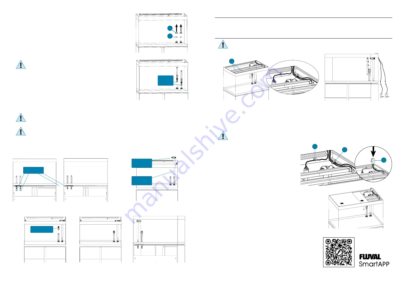
1. Manually unscrew plug (P) and remove plug (Q) from opening (O) (Pict. 1).
IMPORTANT: keep plugs (P) and (Q) for any future use.
2. Slip connector stem (A) fully through opening (O) until it stops (Pict. 2).
3. Open the cabinet. Screw and tighten the ring nut (R) onto the bottom end of stem (A) (Pict. 3).
4. Insert the output nozzle (N) into one end of output stem (B).
5. Insert output stem (B) onto connector stem (A) (Pict. 4).
6. Adjust the height of output nozzles according to your requirement by sliding outlet stem (B)
along connector stem (A).
7. The output nozzles (N) can be easily rotated to divert the water flow where desired.
Direct water jets so as not to let water overflow from the tank.
Avoid directing the water jets towards the LED Strip Lights.
INTAKE SYSTEM INSTALLATION
1. Manually unscrew plug (P) and remove plug (Q) from opening (I) (Pict. 1).
IMPORTANT: keep plugs (P) and (Q) for any future use.
2. Slip the second connector stem (A) fully through opening (I) until it stops (Pict. 2).
3. Open the cabinet. Screw and tighten the ring nut (R) onto the bottom end of
the second stem (A) (Pict. 3).
4. Insert the intake strainer (S) onto connector stem (A) (Pict. 5). The assembly end result
is shown on Pict. 6 and Pict. 7.
The height of the intake strainer is high enough to suit most standard aquarium decorations. When decorating the aquarium,
ensure it remains at least 2” (5 cm) from the gravel bottom at all times to prevent it from sucking gravel or sand and ensure that
no decorations block the passage of water. Ornaments and rocks should be positioned while the aquarium is still dry.
CAUTION!:
Never force Connector Stems (A) sideways, as this may damage the Intake/Output systems and the glass tank.
In the event a different filtration system is used, which does not require the Intake/Output systems supplied with this unit
(e.g. an internal filter), restore the initial conditions by removing the 2 connector stems (A) and closing openings (O) and (I)
with plugs (P) and (Q). Plug (Q) ensures a watertight seal and has to be inserted into its seat by pressing it. Plug (P) is designed
to protect plug (Q) and ensure that plug (Q) remains in its seat properly. Screw plug (P) by hand only until it will no longer go
without forcing it.
DO NOT USE ANY TOOLS, AS DOING SO MAY DAMAGE THE UNIT.
Connector
Stems (A)
Pict. 2
Pict. 1
FLUVAL FILTER & HEATER INSTALLATION, USE AND MAINTENANCE
Please refer to the instruction manual of the Fluval filter/heater. Do not attempt to set up the Fluval filter/heater without
reading and following the instruction manual. If it is missing or unusable, contact the store or Hagen Customer Service.
LED STRIP LIGHTS INSTALLATION INSTRUCTIONS
WARNING:
Disconnect the plug of all electrical equipment used for the aquarium, before placing your hands in aquarium
water and/or performing any maintenance of any kind.
INITIAL START-UP
1. Carefully place the LED Strip Lights (C) on the runner of the top frame in the final position.
2. Pull the LED Strip cables out of the tank (Pict. 8).
3. Hook up the lighting unit to the LED driver with its connector (Pict.9).
WARNING:
Do not plug in the LED Strip Lights if there is water on parts not intended to be wet.
OVER RIM CABLE GUIDE
The power cables of the heater and the LED Strip Lights will be routed out
through the back of the aquarium using the provided over rim cable guide
which can be placed on the right or on the left. (TIP: Heaters are most effective
when positioned near the filter output stem).
1. Place the electrical cable hooks (D) where most appropriate, by sliding
them in the lower runner of both rails (Pict. 10) and pull
the cables out of the tank.
2. Apply the over rim cable guide (E) across the glass of the tank.
PLACING THE SLIDING COVERS ON THE TANK
Peel off the protective film from the two aquarium covers.
1. Lay the narrow cover in the lower sliding surface of the runners (support rails).
2. Lay the wider cover in the upper sliding surface of the runners (support rails).
3. If using Fluval PF2 Fish Feeder, remove one of the two ventilation grills to house the feeder.
SWITCHING THE LED STRIP LIGHTS ON
Plug in the units and use a smartphone or tablet with the FluvalSmart App
downloaded to connect to them. The FluvalSmart App can be downloaded from
the iOS or Android app stores or scan the QR code to download.
Use exclusively the LED drivers supplied with the LED Strip Lights.
In all cases, make sure that the LED drivers specifications comply to the
specifications indicated in the LED Strip Lights identification codes table below.
Pict. 8
Pict. 9
Ring Nuts (R)
Pict. 3
Pict. 4
Pict. 5
Pict. 6
Pict. 7
Output
Nozzles (N)
Output
Stem (B)
Intake Strainer (S)
P
Q
C
Pict. 10
D
D
E


