接收机操作说明
Receiver operation instruction
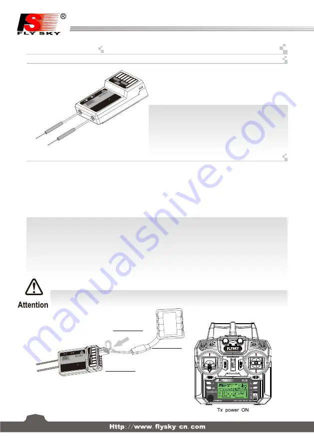
对码线
Bind cable
接收机
Receiver
电池
Battery
14
对码
Binding Setup
接口说明
Port Setup
所有的发射机和接收机,在出厂前都已对码,无需再次对码,若您需要与另一发射机进行对码和使用,
请按以下方法操作:
1.
发射机装上电池,打开电源;
2.
进入主界面,选择
接收机设置
功能。点触
对码
进入对码状态;
3
. 用产品包装所配的对码线,插入接收机
B
/
VCC
通道;
4.
使用
4.0-6.5VDC
电源,按正确极性,插入
CH1- CH6
的任一通道,即可进入对码状态,此时
LED
灯闪烁;
5.
成功对码后,发射机会自动退出对码状态;
6.
拔掉对码线,重启接收机
LED
常亮,此时即可插入舵机及其它数据采集模块,检测其工作是否正常;
7.
如果对码失败,可重复以上动作,重新对码。
(
Pic 12.1)
(
Pic 12.2)
CH1-CH6
:
表示接收机的相应通道;
Bind,VCC
:
表示用于对码和输入电源的通道;
OUT
:
表示输出PPM数据的
i
-
BUS
接口,用于连接串行总线接收
机,扩展通道;
IN
:
表示各种传感器数据的输入接口,数据采集模块可随意串接;
CH1
/
PPM
:
表示
CH1
输出通道兼有
PPM
信号输出功能
CH1-CH6:
represent relevant channel of transmitter.
Bind,VCC:
represent the channel used for matching and input
power respectively.
OUT:
Represent i-BUS port of outputting PPMS data and be used
for
connecting the serial bus
receiver to expand channels.
IN:
Represent input ports of all kinds of sensor data,
and data
acquisition modules can be connected in serial optionally.
All receivers are bound to their respective transmitter at production time. If you want to bind it with another transmitter,
please follow the steps below:
1. Install the battery in the transmitter, and turn on the power.
2. Open the main menu, and select "
RX setup
" function in the second page, then touch "
Bind with a receiver
" to enter bind mode.
3. Insert the standard bind cable into the power supply channel.
4. Connect the 6VDC power connector to any channel from CH1 to CH 6 with correct polarity to enter bind mode, The receiver
LED will flash at this time.
5. The transmitter will exit the bind mode automatically after having successfully bound with the transmitter.
6. Pull off the bind cable and restart the receiver. Please connect the servos and other telemetry modules to the receiver to check
if everything operates normally.
7. If anything is wrong, please repeat the above steps to bind again.
注意:配对好的发射机与接收机,当发射机或接收机因误操作而进入对码状态后, 会出现不能遥控的现象,
一般情况下,关闭电源重开机即可恢复正常,倘若还是不行,则需要重新对码。
Notice: The bound transmitter and receiver will work abnormally if the transmitter or the receiver enters the binding state
by mistake. In other words, the receiver cannot be controlled by the transmitter. If so, you need to restart the transmitter
and the receiver.
5
15
CH1/PPM
: output of channel 1 or PPM output.
(Please see the RX setup)
SERV
O
SENS
CH
5
CH
6
B/
VC
C
CH
2
CH
3
CH
4
P
PM
/C
H
1
i-BU
S
A
LE
D
UP
DAT
E
FS
-IA
6B
6 CH
ANN
ELS R
ECE
I VE
R
2.4
GH
z
4.0
-6.
5V
/D
C
4
SE
RV
O
SE
N
S
CH5
CH6
B/VCC
CH2
CH3
CH4
PPM/CH1
i-
BU
S
A
LED
UPDATE
FS-IA6B
6 CHANNELS R
ECEI VER
2.4
GHz
4.0-6.5V/DC


