background image


Q120 TV Maintenance Manual


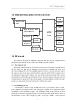
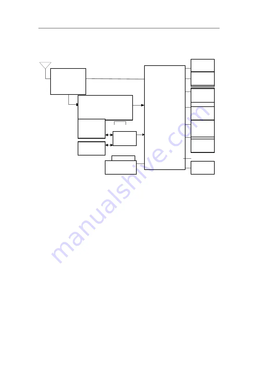
1.2 Detailed Description of Circuit Chart 
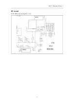


1.3 RF circuit 

This  phone  is  designed  on  MTK6252  platform.  RF  main  chip  is  intergraded  into 

MT6252, PA use 

RPF88162B-TB

, TCXO uses 26MHz crystal oscillator. 

(1)    Receiving circuit 

The GSM or DCS signal received from a base station via antenna is inputted from 

the  pin  U102  27,  and  sent  to  MT6252.  The  signals  are  amplified  by  their  own 
low-noise  amplifier  (LNA).  The  amplified  signal  is  sent  to  a  down  converter,  where 
the signal is mixed with local oscillation (LO) output from RX VCO to generate zero 
intermediate frequency (ZIF) signals. The zero-IF signal passes through a filter and is 
amplified by programmable gain amplifier (PGA), then the signal is outputted to I and 
Q demodulator to generate I/Q base band signals. The demodulated I and Q base band 
signals are outputted to the base band part for further processing. 


(2) 

Transmitting circuit 

A  transmitter  consists  of  I/Q  modulation  circuit,  up-conversion  mixer  circuit, 

power amplifier and duplex switch. The I/Q signal is inputted to be performed signal 
modulation  as  the  modulation  signal.  The  modulated  TXIF  signal  restrain  its  third 
harmonic by harmonic suppression filter. The follow-up TXIF signal will be sent to a 
discriminator  on  the  offset  frequency  phase  lock  loop  (OPLL).  Then  perform 
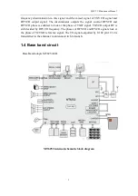
射频

PA

U102

高频滤波

U103

CPU

U201

摄像头

按键板

马达

SIM

SIM

切换
开关

麦克

扬声器

LCD

蓝牙

FM

RF PA+switch   

U102 

High  Frequency  Filter 

U103/U104/U105 


SIM card 

Switch 

Blue Tooth 

Speaker 

MIC 

Camera 

Keypad 

Board 

Motor 


CPU 

U202 

SIM card 

Summary of Contents for Q120 TV

Page 1: ...Q120 TV Maintenance Manual 1 Q120 TV Maintenance Manual Document Name Q120 TV Maintenance Manual Version V1 0 Draft date Document code...

Page 2: ...Fault maintenance 8 3 Trouble shooting and flow chart 9 3 1 Unable to power on the handset 9 3 2 No ring tone 10 3 3 LCD display fault 11 3 4 Charging fault 12 3 5 Camera fault 13 3 6 Fail to identif...

Page 3: ...Q120 TV Maintenance Manual 3 1 Circuit diagram instruction 1 1 Main board explored view...

Page 4: ...and is amplified by programmable gain amplifier PGA then the signal is outputted to I and Q demodulator to generate I Q base band signals The demodulated I and Q base band signals are outputted to th...

Page 5: ...RFVCO phase is enabled to lock at the phase of TXIF signal TXVCO output RF is still decided by RFVCO frequency The phases of RFVCO and IFVCO signals lock at the phase of VCTXO reference signal The TX...

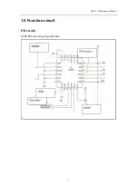
Page 6: ...Q120 TV Maintenance Manual 6 1 5 Function circuit FM circuit U802 FM receiving chip RDA5802E...

Page 7: ...Q120 TV Maintenance Manual 7 BT circuit U701 BT receiver chip MT6612CN L...

Page 8: ...ry important work during the final production of cellular phones The speed and quality of repairing decides the yield and production efficiency The repair idea is very important for a good repairing t...

Page 9: ...Q120 TV Maintenance Manual 9 3 Trouble shooting and flow chart 3 1 Unable to power on the handset...

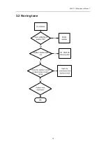
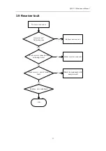
Page 10: ...Q120 TV Maintenance Manual 10 3 2 No ring tone...

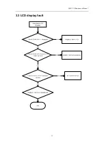
Page 11: ...Q120 TV Maintenance Manual 11 3 3 LCD display fault...

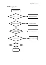
Page 12: ...Q120 TV Maintenance Manual 12 3 4 Charging fault...

Page 13: ...for damage Failure to use camera OK Replace new camera Yes Check if camera is soldered or assembled well No Yes Solder camera connector or Re assemble camera Check camera circuit for fault No Yes Mark...

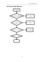
Page 14: ...Q120 TV Maintenance Manual 14 3 6 Fail to identify SIM card...

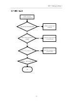
Page 15: ...Q120 TV Maintenance Manual 15 3 7 MIC fault...

Page 16: ...at is assembled correctly Keypad doesn t work correctly OK Paste the DOME or assemble keymat again Yes Is there any dirty on keypad surface No Yes Clean keypad surface and test No Replace new mainboar...

Page 17: ...er ok No broken wire No voice in receiver OK Replace new receiver No Check receiver connector for soldering defect Yes Yes Solder receiver connector No Replace new mainboard No Check receiver circuit...

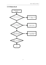
Page 18: ...Q120 TV Maintenance Manual 18 3 10 Vibrate fault...

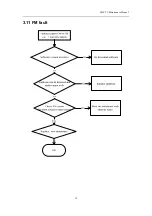
Page 19: ...Q120 TV Maintenance Manual 19 3 11 FM fault...

Page 20: ...Is RF antenna assembled correctly No RF signal OK Re assemble BT anntena No Is the phone set into Flying mode Yes Yes Return to Normal mode No Replace new mainboard No Check RF circuit for any fault...

Page 21: ...Failure to read T flash card OK Re insert T flash card No Check the T flash card is ok Yes No Replace new card Yes Replace new mainboard No Check card socket is clean and no physical fault No Clean so...

Page 22: ...ne OK Replace new earphone No Check earphone connector for soldering defect Yes Yes Solder earphone connector No Replace new mainboard No Is there any foreign matter in earphone connector Yes Clean or...

Page 23: ...Q120 TV Maintenance Manual 23 3 15 Unable to use USB END...

Reviews: