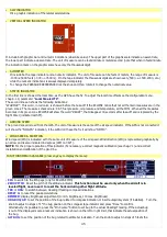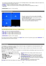
continuous and fluid indication. Provided that GPS receiver have a good satellites reception, the tracking
indication (also called as Course) is very accurate and compensated from wind.
NOTE:
The GPS tracking is not valid when stationary or for speed below 20 km/h, in this case the indication remains
fixed to the last valid received data.
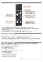
To change the bug select “
HDG BUG/AP
” in the menu bar or, if you have autopilot system, rotate the “HDG/TRK”
knob in the ACU panel.
•
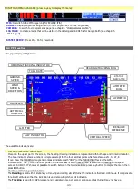
TURN RATE:
Graphical indications of the turn rate. To set the full scale see “Configuration menu”, chapter 6.1.8.
•
AIR SPEED:
The Air speed is represented with both tape and numeric indicator. The unit of measure can be km/h, Mp/h or knots. The
range of measure is from 30 to 470 km/h (16~254 knots or 18~292 mph). Below 30 km/h of air speed the indication remain
fixed to zero.
The speed thresold that define the coloured zone of the tape indicator are those previously set in “ASI GAUGE SETUP”.
There are also the two indication marks for the Vx and Vy speeds.
•
ATTITUDE INDICATOR:
With 360° continuous operation in both pitch and roll. Above and below the horizon line, major pitch marks and numeric
indicators are shown for every 10°, up to +/- 40°. Minor pitch marks are shown for every 5°.
The
roll scale
show inclinations from -60 to +60°; mark lines are shown for the following inclination:
The colors used for the attitude indicator are brown for the ground and sky blue for the sky. The zero is represented by the red
line.
IMPORTANT NOTES ON USING attitude indicator:
•
The attitude indicator may loose accuracy during the flight for the following causes:
- You have exceeded the maximum allowable turn rate on one or more axis (150° per second)
- Rapid temperature changes or temperature outside the operating limit (-20°C~+70°C).
- Continuous maneuvering at high accelerations, with absence of leveled flight attitude for long periods of time.
•
Never use the attitude indicator as a reference for flight manoeuvres.
•
Never use the attitude indicator as a reference in absence of visibility.
•
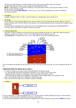
G-METER:
It show accelerations in g, with both graphical bar (-2~+4 G) and numeric indicator (absolute value in G). It also indicate the
maximum and minimum peak accelerations reached (see picture above).
To reset the peak accelerations press any buttons to display the menu and then select with the knob the “
RESET G
” function.
44
Max peak
Min peak
0°
10°
20°
30°
45°
60°
-10°
-20°
-30°
-45°
-60°
Zero dell'orizzonte
Summary of Contents for Eclipse
Page 6: ...ECLIPSE PART I INSTALLATION 6 ...
Page 7: ...2 Dimensions 7 ...


