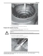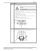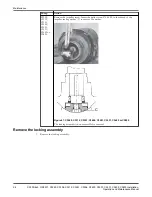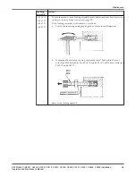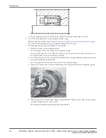
b) Fit the locking assembly (well-oiled) in the impeller hub without tightening any screws.
2. For C3300/6X5, tighten the screws manually in three stages.
Tighten using the sequence that is shown in
Sequence for tightening or loosening locking assembly bolts
(page
99), until the locking assembly keeps the impeller/impeller hub in place.
3. For all pump models except C3300/6X5, fit the impeller:
a) Place the washer over the locking assembly.
See
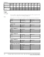
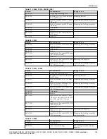
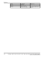
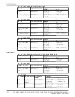
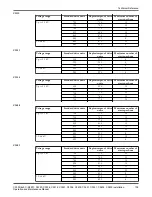
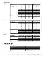
(page 102) for the washer for the respective pump.
For the correct position, use an Allen key through one of the slots in the washer and into one of
the "light-colored" screws in the locking assembly.
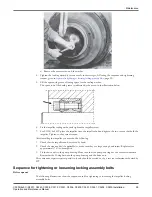
b) Fit the impeller screw, or the screw unit (with hydraulic tool if applicable), through the center hole
in the washer and into the shaft end.
See
(page 102) for the screw/screw unit for the respective pump.
c) Tighten the centre screw so that the washer keeps the locking assembly and the impeller in place.
d) When the impeller is firmly seated, slightly tighten the three "light-colored" screws in the locking
assembly through the slots in the washer.
This keeps the impeller in place against the shaft shoulder.
Maintenance
98
C3300/6x5, C/R3231, C3240, C3306, C3312, C3351, C3356, C3400, C3501, C3531, C3602, C3800 Installation,
Operation and Maintenance Manual


