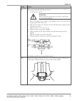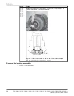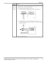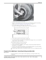
e) Remove the center screw and the washer.
4. Tighten the locking assembly screws evenly in three stages, following the sequence and tightening
torques given in
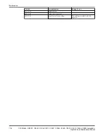
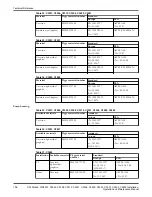
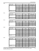
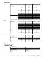
Sequence for tightening or loosening locking assembly bolts
(page 99).
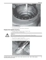
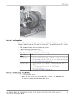
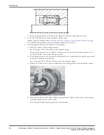
5. Fill the space with grease, allowing space for the sealing washer.
The space to be filled with grease is indicated by the arrow in the illustration below.
6. Fit the impeller sealing washer and tighten the impeller screw.
7. For C3300/6x5 HT: place the impeller onto the impeller hub and tighten the two screws that hold the
impeller. Tighten to the correct torque.
After installing the impeller you must do the following:
1. Check that the impeller can be rotated by hand.
2. Check the zinc anodes (if applicable) to make sure they are large enough and intact. Replace after
approximately 75% consumption.
3. Fit the drive unit to the pump housing. Make sure that the pump housing has the correct orientation.
Remember the O-ring between the pump housing and the drive unit.
More extensive repairs require special tools and should be carried out by a service technician authorized by
ITT.
Sequence for tightening or loosening locking assembly bolts
Bolt sequence
The following illustrations show the sequence used for tightening or loosening the impeller locking
assembly bolts.
Maintenance
C3300/6x5, C/R3231, C3240, C3306, C3312, C3351, C3356, C3400, C3501, C3531, C3602, C3800 Installation,
Operation and Maintenance Manual
99


