11
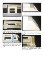
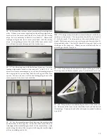
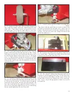
C6. Reinsert the cut foam center piece along the fuselage back
plate. If there is any excess overhang on the trailing edge, make a
mark and cut the excess until the back is flush with the trailing
edge. Sand as necessary to obtain a nice flush fit. Remove the
fuselage and glue the foam center piece flush with the trailing
edge. Avoid getting glue into the sides of the foam center piece.
You will need to route this area out later for the canon.
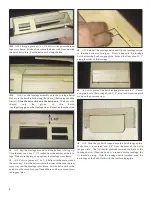
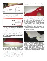
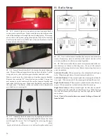
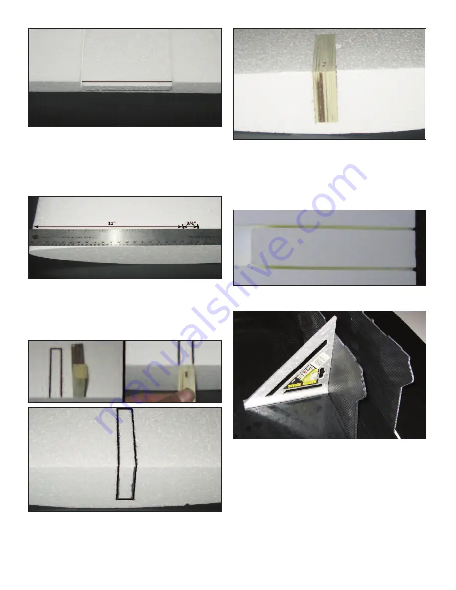
C7. Lay the wing core with the bottom facing up. From the
leading edge make a mark on the wing at 11” and 11 3/4”. To
obtain an accurate measurement, you can butt the leading edge of
the wing against a square, then butt the ruler against the same
square. You can also use a wall on the leading edge to serve the
same purpose if a square is not available.
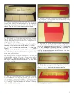
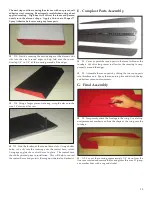
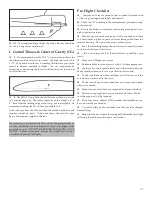
C8. Lay the assembled gear block between the marks scribed
on the bottom of the wing core. Extend the lines around the out-
side edges of the assembled gear block. In the same fashion, scribe
marks along the side of the wing core following the smaller edges
of the assembled gear blocks.
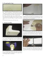
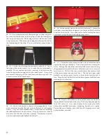
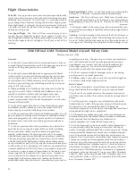
C9. Using a rotary tool with a router attachment cut the foam
inside your line marks. The top portion should be at a depth of
11/16th of an inch. The side portion of the cut should be set at 1”
depth. Make sure you start your cuts inside your lines and test fit
the gear block often. The final fit should be snug and flush with
the edges of the wing core. When you are satisfied with the fit,
glue the gear blocks into place.
C10. Use a rotary tool to notch out 4mm of the gap between
the wing core and the foam center piece. Test fit the canon turrets.
C12. Temporarily insert the fuselage and test fit the canon tur-
ret. The front of the canon turret should be flush with the back of
the fuselage. Continue to make the cut deeper as needed to obtain
a good fit.


