background image

Assembly Instructions

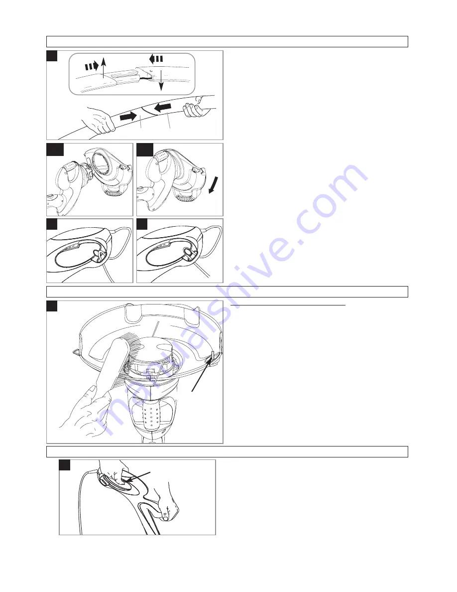
Shaft Assembly (A)
1. Locate the lower shaft (A1) into the upper shaft (A2).
2. Grasp firmly and hold steady the lower shaft.  Locate

the upper shaft and snap together firmly.

The unit is correctly assembled when the gap be-
tween the upper and lower shaft has been closed.

Safety Guard Assembly (B1) & (B2)
1. Locate the safety guard over the cutting head.  Ensure

the nylon line is fed through the hole in the safety
guard as illustrated in fig B1.

2. Push into location and turn safety guard in the direc-

tion illustrated in Fig B2, until a click is heard and the
safety guard is securely locked in position.

ENSURE THE SAFETY GUARD IS SECURELY IN
PLACE BY ATTEMPTING TO TWIST GUARD.

Cable Restraint (C) & (D)
1. Form loop in mains cable and push the loop through

the slot as illustrated in picture (C).

2. To secure, position loop over the hook and pull the

cable back through the slot as illustrated in picture (D).

A

1

2

Starting and Stopping

1

2

C

D

F

WARNING
Cutting head continues to rotate after the trimmer has
been switched off.

To start your trimmer
Squeeze the switch lever (F).

To stop your trimmer
Release the switch lever (F).

B2

B1

Double Auto Feed System

How the automatic line feed works (E)
1. When initially switching on the trimmer, a small length

of line is fed out.  

2. A ‘clattering’ noise will be heard when the two nylon

lines hit the line cutter.  DO NOT BE ALARMED this is
quite normal. After approximately 5 seconds the line
will be cut to the correct length and the noise will re-
duce as the motor reaches full speed.

Make sure the motor is up to full speed before trim-
ming or edging.

3. If the noise of the nylon line being cut cannot be heard,

more line will need to be fed out.

4. To feed more line, it is first necessary to to allow the

motor to stop completely, then re-start, allowing the
motor to reach full speed.

5. Repeat step 4. until you hear the lines hitting against the

cutter.  (Do not repeat this procedure more than 6 times)

6. If problems are experienced with the automatic line

feed refer to Fault Finding Chart.

E

line cutter

Summary of Contents for PWT23

Page 1: ...IMPORTANT INFORMATION Read before use retain for future reference Original Instructions Power Trim ...

Page 2: ...nts or hazards occurring to other people or their property Electrical 1 We recommend the use of a Residual Current Device R C D with a tripping current of not more than 30mA Even with a R C D installed 100 safety cannot be guaranteed and safe working practice must be fol lowed at all times Check your R C D every time you use it WARNING When using the product the safety rules must be followed For y...

Page 3: ...rage 1 Keep all nuts bolts and screws tight to be sure the trimmer is in safe working condition 2 Replace worn or damaged parts for safety 3 Only use the replacement cutting line specified for this product 4 Only use replacement parts and accessories recom mended by Husqvarna UK Ltd 5 After any maintenance in dealing with the cutting line always return the product to its normal operating po sition...

Page 4: ...ting and Stopping 1 2 C D F WARNING Cutting head continues to rotate after the trimmer has been switched off To start your trimmer Squeeze the switch lever F To stop your trimmer Release the switch lever F B2 B1 Double Auto Feed System How the automatic line feed works E 1 When initially switching on the trimmer a small length of line is fed out 2 A clattering noise will be heard when the two nylo...

Page 5: ... direction indicated in Fig K 5 To return to trimming mode depress the locking button and twist head clockwise An audible click will con firm that the head is locked Ensure the button has re turned to its original position G J H How to trim and edge 1 2 1 K To manually feed the nylon line M 1 If required line can be fed out manually 2 To operate press and release manual line feed button whilst gen...

Page 6: ... line To replace nylon line For your convenience it is recommended you buy spool and line complete Nylon line only is also available Both are available from Husqvarna UK Ltd stockists To fit spool and line complete 1 Remove the cap 2 Remove old spool 3 Place new spool into spoolholder with cut out areas of the spool in line with eyelets as shown in figure P 4 Release one line from cleat and feed l...

Page 7: ...se contact your local council office your house hold waste disposal service or the shop where you purchased the product Replacement Parts Spool and Line Reference no FLY021 Part no 513937190 If any part is found to be defective due to faulty manufac ture within the guarantee period Husqvarna UK Ltd through its Authorised Service Repairers will effect the repair or replacement to the customer free ...

Page 8: ...ple of the above product s corresponds to the Value ah given in the table 2000 14 EC The Measured Sound Power LWA Guaranteed Sound Power LWA values are according to the tabulated figures Conformity Assessment Procedure Annex VI Notified Body Intertek Cleeve Road Leatherhead Surrey KT22 7SB England Ulm 25 08 2011 P Lameli Global R D Director Hand held Keeper of technical documentation Type Width of...

Reviews: