background image

3

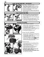
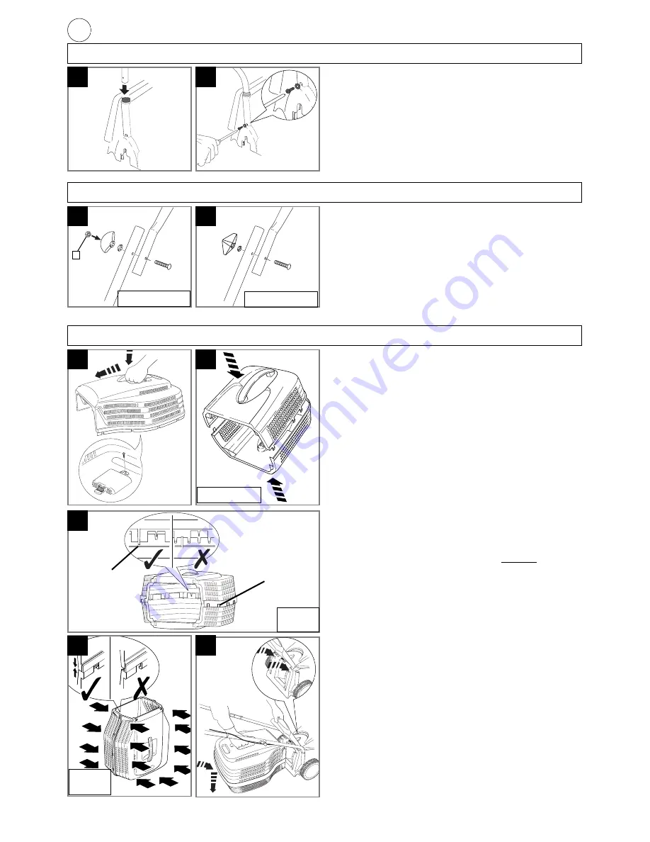
Lower Handle Assembly - RE420/420c

Lower Handles - RE420/420c (C1, C2)

1. If your product has Cutting Height with levers

(see

Cutting Height Adjustment)

, ensure the lever is at

the Highest Cut Height before following steps 2 & 3.

2. Insert lower handles into deck as shown in Fig 

C1

.

3. Push each handle firmly down until it is located

securely into the deck 

(C2)

.

4. Insert screw through the washer and into holes using

a pozidrive screwdriver and tighten fully into deck as
shown in Fig 

C2

.

C1

C2

Fitting Upper Handles to Lower Handles (D & E)

1. Ensure the upper handle is located correctly with

the lock-off button on the switchbox uppermost

2. Ensure the upper handle and the lower handle are

aligned correctly.

3. Insert the nut into the handle knob. (if applicable) 

(D1)

4. Fit the bolts, washers and handle knobs.
5. Fit the cable to the handles with the clips provided. Make

sure the cable is not trapped between the handles.

Upper Handle Assembly

D

E

Venturer 370

RE420/420c

Grassbox Assembly

F

G

Venturer 370

Grassbox Assembly - Venturer 370.

1. Insert the grassbox handle into the top of one of the

grassbox halves.  Press firmly down and forward until
the handle clicks into position 

(F)

2. Turn the grassbox half over and insert screw into hole

(as illustrated in fig F)

and tighten fully.

3. Locate grassbox upper into grassbox lower

(G)

.  Align

clips, ensure all clips are correctly located.

4. Clip the two halves together.
5. Ensure all clips are securely connected.

Grassbox  Assembly - RE420/RE420c

1. Insert the grassbox handle into the top of one of the

grassbox halves.  Press firmly down and forward until
the handle clicks into position 

(F)

2. Turn the grassbox half over and insert screw into hole

(as illustrated in fig F)

and tighten fully.

3. Position the two grassbox halves together and press

each location point 

(H)

into position 

without

fully con-

necting the clips.  When the location points are
matched correctly firmly press the grassbox together
until all clips are securely connected.

(J)

Fitting the Grassbox

1. To attach the grassbox to your lawnmower, lift the

safety flap 

(K) 

and make sure the discharge chute is

clean and free from debris.

2. Locate fully assembled grassbox onto 2 location

points at the rear of the deck. 

(K)

3. Locate safety flap onto the top of the grassbox.

Ensure the grassbox is securely located.

•  Removal is the reverse procedure.

• Please Note:- Ensure no gap remains between

the safety flap and the grassbox.

• Where grass collection is not required you can

use the lawnmower without the grassbox.  Ensure
the safety flap is fully closed.

J

K

H

RE420
RE420c

RE420
RE420c

location
point

clips

a

1

Summary of Contents for VENTURER 370

Page 1: ...IMPORTANT INFORMATION Read before use retain for future reference For all customer enquiries or for replacement parts contact 01325 300303 www flymo com eop customer services electrolux co uk ...

Page 2: ... signs of damage or ageing 3 Do not use the lawnmower if the electric cables are damaged or worn 4 Immediately disconnect from the mains electricity supply if the cable is cut or the insulation is damaged Do not touch the electric cable until the electrical supply has been disconnected Do not repair a cut or damaged cable Replace it with a new one 5 Your extension cable must be uncoiled coiled cab...

Page 3: ...ese connectors be used for earthed products All Flymo connectors and cables are of splashproof con struction They are not waterproof and must not be left outside permanently nor should they be submerged or immersed in water Do not let cable lay or trail through pools of water or splashed with water from hose pipes MAINS PLUG REPLACEMENT IMPORTANT If the plug supplied is cut off it should be destro...

Page 4: ... over and insert screw into hole as illustrated in fig F and tighten fully 3 Locate grassbox upper into grassbox lower G Align clips ensure all clips are correctly located 4 Clip the two halves together 5 Ensure all clips are securely connected Grassbox Assembly RE420 RE420c 1 Insert the grassbox handle into the top of one of the grassbox halves Press firmly down and forward until the handle click...

Page 5: ... and hold the lock off button P on the switch box then squeeze one of the Start Stop levers towards the upper handle Q 7 Continue to squeeze the start stop lever towards the upper handle and release the lock off button 8 Lower the lawnmower to its proper operating position and commence mowing NOTE There are two start stop levers fitted Either one can be used for starting the lawnmower IMPORTANT Do...

Page 6: ...gs T2 T7 Cutting System Maintenance Removing the Blade and Fan 1 To remove the blade bolt hold the fan firmly and with the spanner provided loosen the blade bolt by turning it anti clockwise U 2 Remove the blade bolt blade and fan 3 Inspect for damage and clean as necessary Fitting the Blade and Fan 1 Ensure the fan is located correctly V 2 Fit the blade to the fan with the sharp edges pointing aw...

Page 7: ...actical components manufactured in the most environmentally responsible manner according to company procedures and with the potential for recycling at the end of the products life Packaging is recyclable and plastic components have been labelled where practical for categorised recycling Awareness of the environment must be considered when disposing of end of life product If necessary contact your ...

Page 8: ...SO 5349 as a guide The maximum weighted root mean square value of vibration recorded at opera tor s hand position was Type of Cutting Device Rotary Blade Identification of Series See Product Rating Label Conformity Assesment Procedure ANNEX VI Notified Body I T S Cleeve Road Leatherhead Surrey KT22 7SB England Other Directives 98 37 EEC 89 336 EEC 73 23 EEC applicable standards EN60555 2 1987 EN60...

Reviews: