background image

3

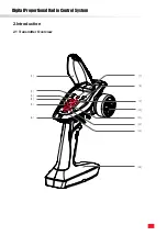
[1]

Panel flip cover

[10] Wheel angle, the maximum rotation of the steering wheel is 

35 degrees from center to left or right (CH1)

[2]

Steering reverse switch (ST.REV)

[11]

Throttle trim  (TH.TRIM )

[3]

Power indicator LED (R. LED)

[12]

Steering D/R  (ST.D / R )

[4]

Status indicator green LED (G.LED)

[13] Power switch

[5]

Two-colors LED battery 

power level display 

(Car battery)

[14] Base, 4 * AA battery compartment

[6] Lanyard hole

[15]

Three-position switch (CH3)

[7]

Bind button (BIND)

[16]

Key Switch SW2 (CH4) [Please operate this function by 

flipping]

[8]

Throttle reverse (TH.REV)

[17] Throttle trigger, has a total throw of 12 degrees, 12.5 

degrees forward, and 12.5 degrees backward (CH2)

[9]

Steering trim (ST.TRIM )

[17]

[15]

[16]

Summary of Contents for FS-G4P

Page 1: ...FS VK G4P HRZ00014 FS G4P Copyright 2021 Flysky Technology co ltd USER MANUAL Digital Proportional Radio Control System...

Page 2: ...sers In order to ensure your safety and the safety of others read this manual carefully before using this product If you encounter any problem during use refer to this manual first If the problem pers...

Page 3: ...witching 9 5 6 Failsafe 9 5 7 Beginner Mode 10 6 VK R4A Receiver Function Instructions 11 6 1 Attentions 11 6 2 Use Guidance 11 6 3 Instruction on the binding of the receiver 12 6 4 Protection Functio...

Page 4: ...y of you and others do not operate in the following places Near any site where other radio control activity may occur Near power lines or communication broadcasting antennas Near people or roads On an...

Page 5: ...Digital Proportional Radio Control System 2 2 Introduction 2 1 Transmitter Overview 2 3 4 5 7 8 9 11 12 13 14 6 1 10...

Page 6: ...R 4 Status indicator green LED G LED 13 Power switch 5 Two colors LED battery power level display Car battery 14 Base 4 AA battery compartment 6 Lanyard hole 15 Three position switch CH3 7 Bind butto...

Page 7: ...Antenna 3 CH4 11 LED 4 Headlight interface 12 Motor interface M 5 Left turn signal light interface 13 Motor interface M 6 Right turn signal light interface 14 Battery cable interface 7 Power cathode 1...

Page 8: ...ts Danger Do not expose to excessive heat or liquids Danger Do not drop the battery or expose to strong shocks or vibrations Danger Always store the battery in a cool dry place Danger Do not use the b...

Page 9: ...transmitter into binding state first then the receiver 4 1 Power On However if the receiver needs to be replaced or additional receivers bound follow these steps Note Operate with caution in order to...

Page 10: ...ely counterclockwise When calibration is completed the R LED will be off Car Battery the D3 red keeps on 3 Trigger calibration Pull the trigger back then forward as far as it will go When calibration...

Page 11: ...indicates reverse and the down indicates normal 5 3 Trims The ST TRIM is the trims for CH1 steering and can be multiplexed as Trims of CH3 and CH4 For multiplexing switching mode see 5 5 Mode Switchi...

Page 12: ...M and ST D R buttons for different channels see 5 3 Trims 5 4 D R Function setting Under normal power on quickly press the Bind button twice within 1 Sec to cycle through modes 1 2 3 and 4 The default...

Page 13: ...nge defaults to 1250 1500 1750us Setup To switch between beginner and normal modes first press and hold the channel 4 button and Turn the handwheel to the bottom counterclockwise then turn on the tran...

Page 14: ...time even if it is off It will discharge completely if connect the battery for a long time thus resulting in the failure of the battery or the ESC We are not responsible for any damage caused by this...

Page 15: ...age protection The low voltage protection value is 6 3V When the ESC detects that the battery voltage reaches the low voltage protection value for 2 seconds the output power of ESC will be halved that...

Page 16: ...flashing state When the CH3 key on the transmitter is located at the leftmost end the headlight is off When the CH3 key is located at the middle position the headlight is on When the CH3 key is locate...

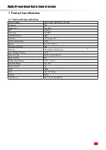
Page 17: ...GHz RF Power 20dBm 2 4GHz Protocol ANT Distance 150m ground Channel Resolution 1024 Battery 6V DC 1 5AA 4 Charging Interface NO Life time According to battery type Low Voltage Warning 4 2V Antenna Typ...

Page 18: ...everse 1 The connection sequence between output line of ESC and motor line 2 The throttle direction of radio is wrongly set 1 Exchange the position of two lines of motor 2 Set throttle direction of ra...

Page 19: ...Digital Proportional Radio Control System 16 9 Package Contents Transmitter 1 Receiver 1...

Page 20: ...he following two conditions 1 This device may not cause harmful interference 2 This device must accept any interference received including interference that may cause undesired operation Caution The m...

Page 21: ...terference that may cause undesired operation of the device L metteur r cepteur exempt de licence contenu dans le pr sent appareil est conforme aux CNR d Innovation Sciences et D veloppement conomique...

Page 22: ...hat interference will not occur in particular installation If this equipment does cause harmful interference to radio or television reception which can be determined by turning the equipment off and o...

Page 23: ...munal collecting point via private persons is for free The owner of old appliances is responsible to bring the appliances to these collecting points or to similar collection points With this little pe...

Page 24: ...Copyright 2021 Flysky Technology co ltd www flysky cn com Release date 2021 06 15...

Reviews: