15
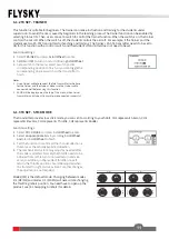
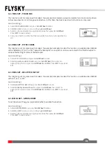
FREQUENCY
To set an apppropriate frequency according to your servos.
Note: Note: When the frequency value is set to 50HZ, it presents the analog servo, and set to 333HZ, it is for digital servo. For other servo,
set the value in the range between 50 and 400HZ.
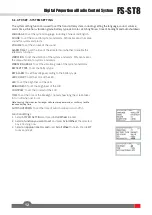
RF STANDARD There are two options available, ANT1WAY one-way and ANT2WAY two-way. If you are using a two-
way receiver, it is recommended to select ANT2WAY two-way, which may bring you a better experience with more
information feedback.
Refer to 4.3 Bind setting for function settings.
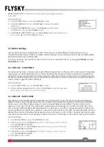
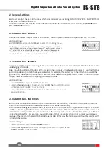
Failsafe is an important safety setting. It can be used to protect the model from loss or reduce the degree of loss
when the receiver loses signal without control. In addition, it plays a role in protecting personnel safety.
You can set the data in case of loss of control for all output channels.
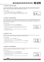
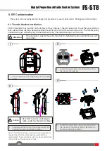
As an interesting feature for two-way communication systems, sensors can be used to send back some information
you need through the receiver.
The transmitter can support up to 15 different types of returned data to provide you with the feedback of seven
basic parameters, i.e., TX VOL(TX voltage), RX VOL(RX voltage), BVD VOL(BVD voltage), SIGNAL(signal intensity),
NOISE, SNR(noise rate) and RSSI.
For BVD function, it is used to detect an external power supply. It is recommended to use this function to monitor
the battery voltage and give an alarm in case of a failure. To perform an alarm by setting alarm values for LOW and
HIGH.
6.2.2 RX SET - FAILSAFE
6.2.3 RX SET - SENSOR
Function settings:
1.
Select
FAIL SAFE
and press
Scroll Wheel
to enter
.
2.
Select
a item you want to set using
Scroll Wheel
.
3.
Select an appropriate item and press
Scroll Wheel to confirm.
Press
EXIT
to
save and exit.
If it is set to ON, the system will show a prompt menu, select OK and press
Scroll Wheel
to confirm. Then you can set a failsafe for each channel.
Notes:
1.
For bus signal types such as PPM/i-BUS/S.BUS, a single or several of these channels are
not allowed to be in OFF mode. The actual signal is held at the last output value when
the channel is set to OFF
2.
Because the S.BUS signal information contains failsafe flag bits, the failsafe settings of
each channel are communicated to subsequent devices by the failsafe flag bits. If the
connected devices support the failsafe flag bit analysis, the failsafe values set for each
channel are output after out of control.
3.
For the signal PPM/i-BUS without failsafe flag bits, it supports the setting of the signal
to OFF mode in case of out of control. After setting to OFF mode, regardless of the
setting of the failsafe of each channel, each channel will be in OFF mode after out of
control. The failsafe function has no default set at the factory and as such must be set
manually.
4.
If no failsafe setting has been set, then the receiver will not output anything when signal
is lost.
Function settings:
1.
Connect a sensor to the receiver via the SENS interface
. At the transmitter
side,
select
SENSOR
and press
Scroll Wheel
to enter
.
2.
Select
a item you want to set using
Scroll Wheel, such as TX VOL, using
Scroll Wheel, you can set it to dispaly on the main menu
, as well as set
a alarm function and its alarm value corresponding to LOW and HIGH
voltage.
3.
Press
EXIT
to save and exit.
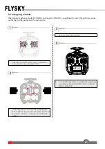
Displays the sensor number, type,
the data returned by this sensor.
The solid icon indicates that the corresponding
sensor has been set on the main menu, and the
hollow icon indicates that the corresponding
sensor is not set.


