background image

FS-ST8

Digital Proportional Radio Control System

24

8. DIY Customization

FS-ST8 transmitter has two sticks in the factory settings, and one is the self-return stick. To use the non-self-return 

stick, please follow the steps below to replace the self-return stick to the non-self-return stick. The throttle spring 

includes two types: setback spring and non-setback spring (the installation steps are the same).

The system can be reconfigured to change stick placement, mount mobile stand,RF adapter or SMA antenna. 

8.1 Throttle Bracket Installation

x5


Attention

•  This operation is only for the self-return stick.It is forbidden to disassemble the non-self-

return stick.

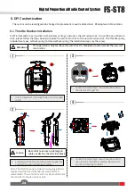
1.     Use a screwdriver to remove the 5 screws marked 

in red. 

3.     Loosen the assembly screws shown above first, 

then remove the gimbal. 

4.     Loosen the assembly screws shown above first, 

then remove  the plate assembly. Be careful to 

ensure no damage to cables. 

2

4

2.     Carefully pull the front and back covers apart. Be 

careful to ensure no damage to cables. 

Note: The throttle spring installation, swapping gimbals 

requires that the transmitter be disassembled and 

reassembled. The instructions will only be provided here, 

the rest refer to the descriptions here.

3

x4

  Caution •  Be careful to ensure no damage to 

cables


or destroy the terminal block. 

Summary of Contents for FS-ST8

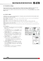
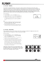
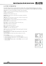
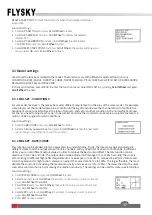
Page 1: ...FS ST8 Copyright 2022 Flysky Technology co ltd USER MANUAL USER MANUAL Digital Proportional Radio Control System...

Page 2: ...l safety as well as the safety of your equipment If you encounter any problems during using please refer to this manual first If the problem is still not resolved please contact the local dealer direc...

Page 3: ...4 4 Stick Calibration 7 4 5 Power Off 7 5 Main menu 8 6 Function menu 9 6 1 Transmitter settings 10 6 1 1 TX SET MODEL 10 6 1 2 TX SET TRAINER 11 6 1 3 TX SET STICK MODE 11 6 1 4 TX SET SYSTEM SETTIN...

Page 4: ...NU MIXES 21 7 FS SR8 Function instructions 23 7 1 Attentions 23 7 2 Binding 23 7 3 RSSI 23 7 4 Updating the Firmware of the Receiver 23 7 5 Failsafe of the Receiver 23 8 DIY Customization 24 8 1 Throt...

Page 5: ...y of you and others do not operate in the following places Near any site where other radio control activity may occur Near power lines or communication broadcasting antennas Near people or roads On an...

Page 6: ...y 11 Carrying Handle 21 Trainer Jack 3 5mm audio head 2 EXIT Button 12 VRB Knob 22 A Reserved Hole for SMA Antenna 3 MENU Button 13 SWC Three position Switch 23 Type C Port 4 T1 T2 Trim Button 14 SWD...

Page 7: ...enu press Scroll wheel after the selection by scrolling Scroll Wheel to enter the editing state In this case you can scroll the Scroll wheel left and right for editing In the detail menu and if no ite...

Page 8: ...e antenna of the transmitter and the antenna of the receiver in operations Otherwise the quality and strength of the radio transmission signal will be greatly reduced resulting in the failure and out...

Page 9: ...the battery compartment 3 2 Installing Receiver and Servo Install the receiver and servo in the following methods Prior to operations please install the battery and connect devices according to the se...

Page 10: ...id damage or injury Note For your safety please turn the transmitter switch and throttle to the safe position Applicable to the FS ST8 transmitter and the FR SR8 receiver Different receivers have diff...

Page 11: ...e calibration is required in case of data offset of the transmitter due to physical wear in long term operations At this time we need to calibrate the output data and neutral angle of the stick thrott...

Page 12: ...e signal strength and TX voltage When the receiver is bound and the voltage of the receiver is 6V then RX6 0V will displayed here Timer Quick access to the menu Select the area and press Scroll Wheel...

Page 13: ...V TAIL For MULTICOPTER CONDITIONS RATE CURVE THROTTLE CURVE and THROTTLE HOLD For ENGINEERING VEHICLE CONDITIONS RATE CURVE THROTTLE CURVE THROTTLE HOLD and TRACK MIX For ROBOT CONDITIONS RATE CURVE T...

Page 14: ...ET It means that this function will reset all the set values of the model parameters and restore the factory settings Function settings 1 In the MODEL menu select the function by scrolling Scroll Whee...

Page 15: ...ICK MODE and press Scroll Wheel to enter 2 Select an appropriate item by scrolling Scroll Wheel and press Scroll Wheel to finish 3 Test the function to confirm all the channel direction is the same as...

Page 16: ...ALA means the same sound for system and alarm VOLUME To set the volume of the sound ALARM TIME To set the time of the idle alarm or whether to enable the idle alarm function VIBRATION To set the vibra...

Page 17: ...Set switches to START STOP and RESET using Scroll Wheel You can also set a throttle trigger value to start the timer to calculate the working time of the throttle after the timer is on 4 For ALARM se...

Page 18: ...NTER and press Scroll Wheel to enter then you can view the related information Function settings Select MORE and press Scroll Wheel to enter then you can view the related information Function settings...

Page 19: ...an appropriate item and press Scroll Wheel to confirm Press EXIT to save and exit If it is set to ON the system will show a prompt menu select OK and press Scroll Wheel to confirm Then you can set a...

Page 20: ...the Serial Bus Receiver FS CEV04 then press the button K1 corresponding to C1 channel of FS CEV04 receiver by a long thin tool After the setting is successful the system will pop up a menu showing suc...

Page 21: ...tion can be divided into two parameters for understanding Firstly the rate can be quickly adjusted in different states to set the output value of certain channels with symmetrical treatment at both en...

Page 22: ...3 4 MDL SET THROTTLE HOLD 6 3 5 MDL SET V TAIL 6 3 6 MDL SET DELTA WING MIX Function settings 1 Select THROTTLE CURVE and press Scroll Wheel to enter 2 Select a point you want to set and press Scroll...

Page 23: ...YROSCROPE Function settings 1 Select DELTA WING MIX and press Scroll Wheel to enter 2 Set ON or OFF to turn on or turn off using Scroll Wheel 3 Select an item and select an appropriate value then pres...

Page 24: ...not be unified In addition there may be different sizes of operator s habitual actions The servo travel function can be used to set the travel amount required for each channel to adjust the correspon...

Page 25: ...nsmitter to finish 4 Set a speed value Press EXIT to save and exit Function settings 1 Select AUX CH and press Scroll Wheel to enter 2 Select a auxiliary channel and press Scroll Wheel to enter the sw...

Page 26: ...2 Set ON or OFF to turn on or turn off using Scroll Wheel 3 Set a switch In the menu select a switch and its corresponding position to finish or you can toggle the corresponding physical switch on th...

Page 27: ...for more than ten seconds until the LED of the receiver operates in three flash one off manner repeatedly then release the BIND button Power on the receiver first then press and hold the BIND button f...

Page 28: ...Attention This operation is only for the self return stick It is forbidden to disassemble the non self return stick 1 Use a screwdriver to remove the 5 screws marked in red 3 Loosen the assembly screw...

Page 29: ...the plate assembly back in its original position then secure it with the original 4 screws 7 Put the bracket to the position which is shown above then secrew it using the screws You can install the s...

Page 30: ...move the two screws which are shown above and remove the bracket 2 Loosen the assembly screws shown above first then remove the plate assembly Be careful to ensure no damage to cables 3 3 Insert the 2...

Page 31: ...1 Take the transmitter apart using a screwdriver remove the 8 screws marked in red 3 Reassembly the transmitter 4 Turn on the transmitter and make sure everything is working as expected via Main menu...

Page 32: ...adjusted angle by this screw nut Device holder introduction How to install the holder How to fix the mobile phone with the holder 2 3 1 To adjust the holder loosen locking knob by turning it anti clo...

Page 33: ...align the screw holes 2 Tighten the four screws to secure the RF module adapters 2 Stealth I O RF module interface RX GND NC S port PPM TX Note The transmitter Stealth I O RF module interface is desi...

Page 34: ...ers and spring spacers in order Then screw in the hexagonal nut and then tighten the antenna post 4 Finally close the back cover Please make sure the wire terminals are in good contact Note You need t...

Page 35: ...Maximum Power 20dBm e i r p EU 2 4GHz Protocol ANT Distance 1000m Air distance without interference Channel Resolution 4096 Battery 1 5AA 4 2S Lipo JST Charging Interface NO Data Output PWM PPM i BUS...

Page 36: ...ineering vehicles Robots Cars or Boats etc Numbers of channel 8 Maximum Power 20dBm e i r p EU RF 2 4GHz ISM 2 4GHz Protocol ANT Resolution 4096 Distance 1000m Air distance without interference Antenn...

Page 37: ...start guide 1 4 Throttle return to center modification parts 1 5 JR RF adapter 1 6 Setback sense throttle modification parts 1 7 Device holder 1 Optional 8 External FS FAR01 2 4G antenna modification...

Page 38: ...o conditions 1 This device may not cause harmful interference and 2 This device must accept any interference received including interference that may cause undesired operation Caution The manufacturer...

Page 39: ...pliances to these collecting points or to similar collection points With this little personal effort you contribute to recycle valuable raw materials and the treatment of toxic substances CAUTION RISK...

Page 40: ...ky Technology co ltd www flysky cn com Release date 2022 04 11 CE FCC ID N4ZST800 Manufacturer ShenZhen FLYSKY Technology Co Ltd Address 16F Huafeng Building No 6006 Shennan Road Futian District Shenz...

Reviews: