background image

HRZ00020&HRZ00017

Digital Proportional Radio Control System

4

3.

Getting Started


Before operation, install the battery and connect the system as instructed below. 

3.1 Transmitter Battery Installation


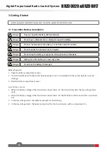
Danger

• 

Only use specified battery (X4 AA batteries).


Danger

• 

Do not open, disassemble, or attempt to repair the battery.

  Danger

• 

Do not crush/puncture the battery, or short the external contacts. 


Danger

• 

Do not expose to excessive heat or liquids. 


Danger

• 

Do not drop the battery or expose to strong shocks or vibrations.


Danger

• 

Always store the battery in a cool, dry place.


Danger

• 

Do not use the battery if damaged.

Battery Type: AA 

1.    Open the battery compartment cover.
2.  Insert 4 AA batteries with the correct polarity. Make sure it is connected with the correct polarity to avoid 

damage. 

3.  Replace battery compartment cover.   
 
Low battery alarm: 
1.     When the battery voltage of the transmitter is lower than 4.2 V, the transmitter enters the low voltage alarm 

state.

2.     When the battery voltage of the transmitter is lower than 3.5 V, the RF function of the transmitter is switched 

off.

3.     In the low voltage alarm, the indicator prompts in slow flashing.
4.     In the low voltage alarm, the buzzer prompts with a short sound cycle, with a cycle period of 1 s.

Summary of Contents for HRZ00017

Page 1: ...HRZ00020 HRZ00017 Copyright 2022 Flysky Technology co ltd USER MANUAL USER MANUAL Digital Proportional Radio Control System...

Page 2: ...safety and the safety of others read this manual carefully before using this product If you encounter any problem during use refer to this manual first If the problem persists contact your local deale...

Page 3: ...scription 7 5 2 Channel Reverse 7 5 3 Trims 7 5 4 D R 7 5 5 Failsafe 7 6 HRZ00017 Receiver Function Instructions 8 6 1 Attentions 8 6 2 Use Guidance 8 6 3 Instruction on the binding of the receiver 9...

Page 4: ...y of you and others do not operate in the following places Near any site where other radio control activity may occur Near power lines or communication broadcasting antennas Near people or roads On an...

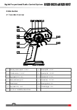
Page 5: ...ng reverse switch ST REV 8 Steering D R ST D R 2 Throttle reverse TH REV 9 Steering trim ST TRIM 3 Key Switch AUX3 CH3 10 Throttle D R TH D R 4 Status indicator red LED 11 Throttle trim TH TRIM 5 Powe...

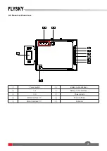
Page 6: ...3 2 2 Receiver Overview 1 Power switch 6 Battery cable interface 2 CH1 7 Battery cable interface 3 LED 8 Power anode 4 Motor interface M 9 Power cathode 5 Motor interface M 10 Antenna...

Page 7: ...r Always store the battery in a cool dry place Danger Do not use the battery if damaged Battery Type AA 1 Open the battery compartment cover 2 Insert 4 AA batteries with the correct polarity Make sure...

Page 8: ...per cycle 3 Fast flashing flashing frequency is 5 Hz 100 ms on and 100 ms off per cycle 4 Indicator response priority from high to low Binding and low voltage alarm 5 The trigger response details of t...

Page 9: ...e sure to disconnect the receiver power before turning off the transmitter Failure to do so may lead to damage or serious injury Follow the steps below to turn off the system 1 Disconnect the receiver...

Page 10: ...ween 900 us and 2100 us Thus the receiver can be cooperatively used for realizing the boat turning function 5 2 Channel Reverse ST REV CH1 direction inversion switch left side normal state right side...

Page 11: ...n the failure of the battery or the ESC We are not responsible for any damage caused by this Make sure the receiver is mounted away from motors or any device that emits excessive electrical noise Keep...

Page 12: ...tage protection The receiver can detect the battery voltage and can realize the battery voltage too low protection function When the battery voltage is lower than 5 6 V the throttle is output in a hal...

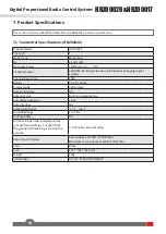
Page 13: ...digital system Channel Resolution 1024 Battery DC 6V 1 5AA 4 Display mode LED display harging Interface NO Antenna Type Built in single antenna Low Voltage Warning 4 2V Data Interface NO emperature R...

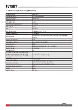
Page 14: ...ency hopping digital system Channel Resolution 1024 Low Voltage Warning Yes Alarm at transmitter Data Interface PWM Antenna Type External single antenna Coaxial antenna Display mode LED display Online...

Page 15: ...HRZ00020 HRZ00017 Digital Proportional Radio Control System 12 9 Package Contents Transmitter 1 HRZ00020 Receiver 1 HRZ00017...

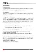
Page 16: ...his equipment complies with Part 15 of the FCC Rules Operation is subject to the following two conditions 1 This device may not cause harmful interference 2 This device must accept any interference re...

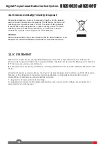
Page 17: ...BATTERIES ACCORDING TO THE INSTRUCTIONS This device contains licence exempt transmitter s receiver s that comply with Innovation Science and Economic Development Canada s licence exempt RSS s Operati...

Page 18: ...ww flysky cn com FCC ID 2A2UNHYMG400 IC 25584 HYMG400 Made in China Manufacturer ShenZhen FLYSKY Technology Co Ltd ADD 16F Huafeng Building No 6006 Shennan Road Futian District Shenzhen Guangdong Chin...

Reviews: