100
17. How transmitter output functions are processed
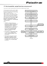
This section contains the Paladin PL18 functional arithmetic logic content.
Control(
Stick, Switch
, etc.)
Func. Rate (AFR)/DR setup
Set by function
Set by channel
Reverse
Channel End
Channel Range
Channel
Mixes
Trim
Subtrim
Channel offset
This figure shows how the system handles
the transmitter output function and how
the various configuration choices/settings
affect the output function.
When you move a transmitter control,
such as a stick or switch, the final output
value of the channel will be calculated
and output in the order shown according
to the setup function:
Func. Rate(AFR)/
DR setup
>
Set by function
>
Mixes
>
Reverse
>
Channel End
>
Channel Range
>
Set by channel.
Notes:
1.
The
Mix
es includes the function
mixing such as
Aileron to Rudder
and
Programming mixes
. The operation
result will be output via
Reverse
,
Channel End
which is superimposed
with other operation results of the
channel with the
Channel Range
operation, and
Set by channel
function operation.
2.
When
Master
of
Programming mixes
is set to a function,
Slave
will be
delayed if
Set by Function
is set for
this function.
3.
After the value of the trim control is
calculated by
Trim Rate
and
Trim
Mode
, then will be superimposed
with other values of this channel, such
as
Subtrim
, before
Channel Range
calculation.


