30
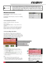
Notes:
1. For the enhanced receiver, before connecting the sensor to the receiver, you need set the output signal type for NPA(Newport A) to
i-BUS-IN via Basic > RX setting > Custom port protocol first.
2. The abbreviations for the Newports are for NPA, NPB, NPC NPD, the receiver supports up to 4 newports.
3. The system only supports one Newport interface is set to i-BUS-IN, and at the same time the other newports cannot be set to i-BUS2.
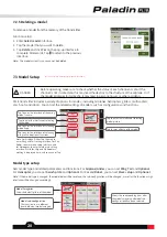
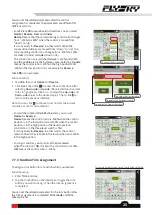
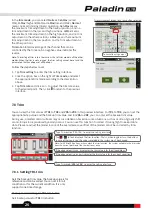
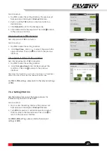
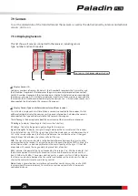
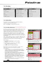
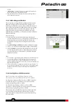
The following descriptions are installations and function settings about some i-BUS sensor modules. Take the FTr10
receiver and the PL18 transmitter as an example, connect the sensor to the SENS interface of the FTr10 receiver, and
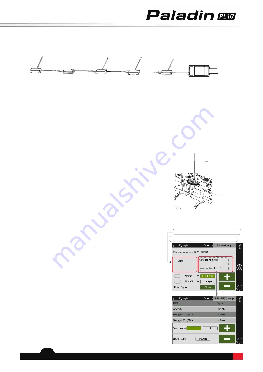
the other sensor can be connected to the IN interface of this sensor in turns. The connection digram between the
senor and the receiver is shown below.
FS-CPD02
FS-CTM01
FS-CVT01
FS-CAT01
FS-CPD01
FTr10
FS-CPD01: Magnetic induction Speed Acquisition Module
Be used to measure the speed of the motor. Monitor the real-time data of detection through the
Sensor
interface.
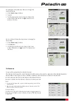
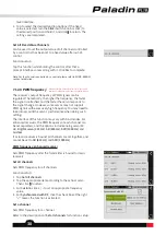
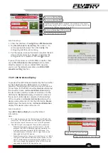
Installation steps:
1. Place the sensor next to the magnet, which is fixed to the
spinning part of a model such as the blades of a plane rotor.
Note: Make sure that the sensor is within 2mm of the magnet and the north
pole or south pole of the magnet is parallel to the sensor.
2. Connect the FS-CPD01 sensor to the
SENS
interface of the
FTr10 receiver.
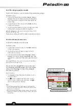
3. Turn on the transmitter and enter
Home1
>
Basic
>
Sensor
.
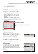
Try to turn the gear around, if the
RPM-SP
value changes,
then the installation is successful, otherwise repeat the above
steps.
Note:
RPM-SP
means the sensor is testing the speed of the motor.
3
is the
sensor ID and refers to the third sensor.
12rpm
is the speed measurement
value.
2 2
Sensor
FS-CPD01 module
Magnet
Gear
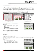
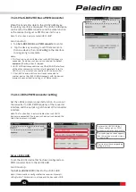
To display the real-time speed of the motor.
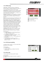
Tap to enter the parameters' setting screen.
The interface of the
RPM-SP[3]
is shown at the right. For the
Alarm
and
extreme value
, refer to the related setting of the
TX
voltage
. For the setting of
RPM
, follow the steps below:
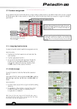
Function setup:
1. Tap to area showed on the picture to enter the setting
interface.
2. Click the function box right to the
Gear ratio
to select it.
Click
+
/
-
to set the appropriate value.
3.
Click
the function box right to the
Wheel CIR
to select it.
Click
+
/
-
to set the appropriate value.
Notes:
1. The gear ratio is the rate of the number of gears of the actual detection
speed to the number of gears of the target monitoring speed.
2. When it is not convenient to install a sensor for a device with the pre-
monitoring speed, you can try to monitor the rotational speed of the
device by testing the rotational speed of the drive components and
setting the appropriate gear ratio. For example, monitor the speed of the
rotating shaft by monitoring the rotational speed of the paddle.
3. For a wheeled vehicle model, the speed of the vehicle can be obtained
based on the set wheel circumference and the rotational speed value of
the wheels.

