99
16.1.4 Logic switch setting
Provide the interface for selecting logic switches. Users
can preview the corresponding component switches
and logical relations of logic switches, and can click the
preview box to enter the logical switch setting interface
to reset the logical switches.
Function setup:
1. Enter the switch assignment interface.
2. Toggle the corresponding physical control on the
transmitter or tap the control name in the interface
to select the control, e.g.,
VRD
.
3. Switch the type mode by tapping
HYS
.
4. Turn the
VRD
to a suitable position, and tap
ON
/
UP
in the green function box on the right to set this
position to
ON
/
UP
.
5. Turn the
VRD
to another suitable position, and tap
ON
/
UP
in the green function box on the right to set
this position to
ON
/
UP
.
6. Click
Posit.
to reverse the switch status.
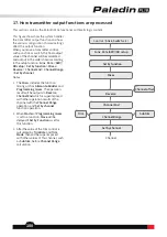
Function setup:
1. Enter the switch assignment interface.
2. Click
LSW
and a pop-up screen appears. Click the logic
switch you want to set, then tap the area to enter the
setting interface. Then you can set a new logic switch.
Function setup:
1. Click
Linear type
to enter the setting interface.
2. Click the appropriate linear type and points. Then
click to return.
• Click
<<
/
>>
to select the point. The current
selected point is shown in green.
• Click
+
/
-
to change the values of
Rate
and
Offset
.
To display the 2 consisted switches of a
LSW
.
Tap to enter the
LSW
setting interface.
To display four groups of
LSW
. Tap to select it.
16.2 Linear setting
This section describes the linear settings of throttle curve and each mixes function. Such as
linear type
or
curve
type
setting (
Throttle cut
,
Pitch curve
,
Throttle needle
and
Pro. mixes
)
.
Note: The on/off of Logic switch is to enable or disable a function.
Notes:
1. After the linear type changes, the linear parameters before the
change are overwritten.
2. The line can be shifted along the Y axis by offset value set.
Note: This function is applicable for version 1.0.65 or above.


