background image


2


2  

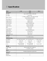
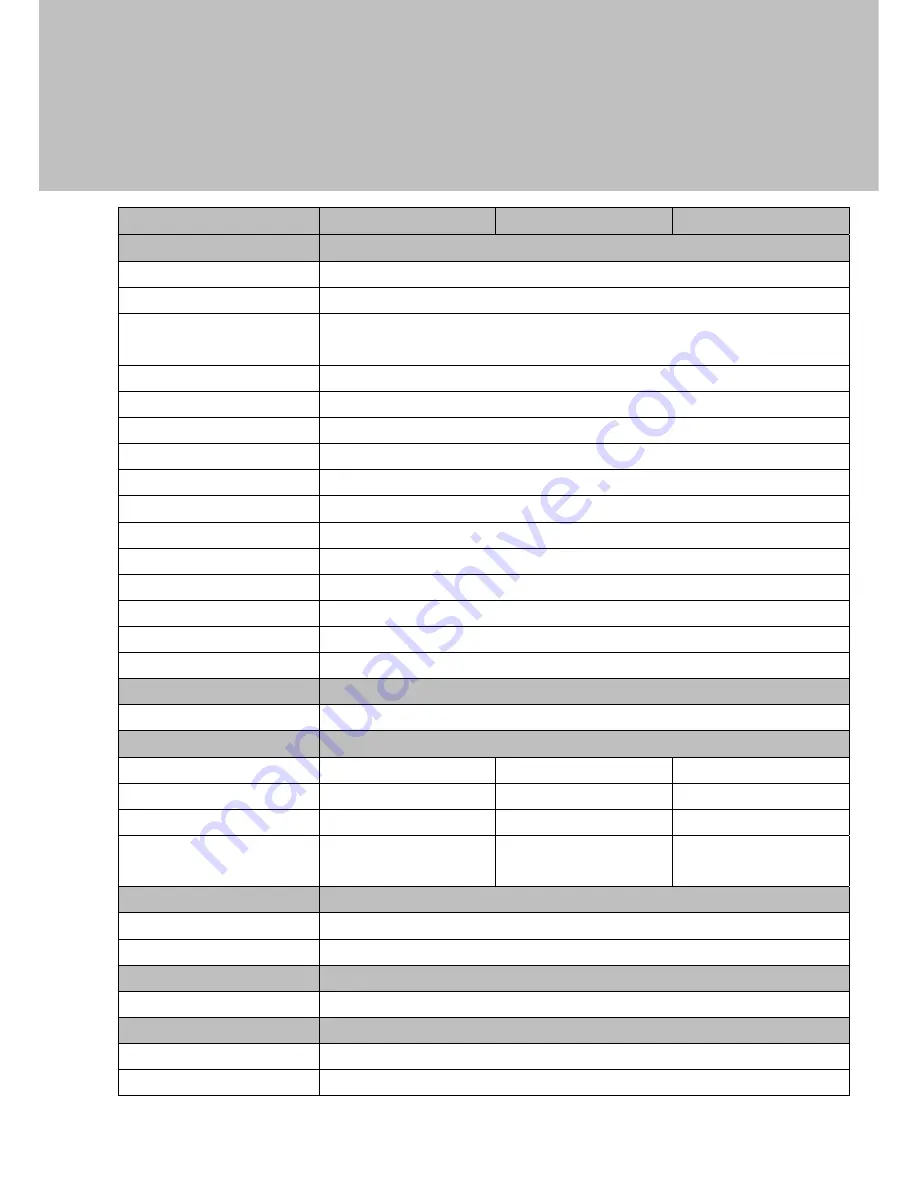
Specification 


Model 

K738 

K746 

K747 

Motherboard 

D35 

Processor 

Celeron J1900 2.0GHz L2 2M (10W) 

Core Logic 

Built-in SoC 

System Memory 

1 x DDR3L SO-DIMM slot, FSB 1066/1333MHz 

Default 4GB RAM (Max 8GB) 

Graphic Memory 

Intel Graphic DX11.1 

LAN1 Controller 

Intel WG I211AT 

LAN2 Controller 

Intel WG I211AT 

Audio Controller 

Realtek ALC662VDO-GR 

I/O Controller 

Winbond NCT6106D 

LVDS Controller 

Realtek RTN2136R 

BIOS Phoenix 

UEFI 

Touch Controller 

ETTI (USB) 

TPM Contoller 

NUVOTON TPM NPCT420 

Watch Dog Timer 

Hardware WDT 

MB Dimension 

185 x 120 mm 

IO Board Dimension 

248 x 64 mm 

Expansion 


Mini PCIe 

1 x miniPCIe half size 

LCD Touch Display 


LCD Display 

18.5" LED Panel (16:9) 

12.1" LED Panel (4:3) 

15" LED Panel (4:3) 

Resolution 

1366 x 768   

1024 x 768 

1024 x 768 

Brightness 

250 nits   

500 nits 

450 nits 

Touch 

True Flat Resistive   

 True Flat P-CAP 

True Flat Resistive   

 True Flat P-CAP 

True Flat P-CAP 

Storage 


m-SATA 32GB 

PCIe full length slot for mSATA only 

HDD 7-pin 

SATA 

connector 

Power 


Power Input 

12-48Vdc (Polarity Reverse Protection) 

Front I/O 


USB 2.0 

Power Button 

Summary of Contents for K738

Page 1: ...Version 1 0 February 2015 K738 K746 747 Panel PC Hardware System User Manual...

Page 2: ...l or consequential damages in connection with the furnishing performance or use of this material This document contains proprietary information that is protected by copyright All rights are reserved N...

Page 3: ...Low Voltage Directive FCC This device complies with part 15 of the FCC rules Operation is subject to the following two conditions 1 This device may not cause harmful interference 2 This device must a...

Page 4: ...vice should be taken to the waste collection centers for activation of the treatment collection recycling and disposal procedure To prevent possible harm to the environment or human health from uncont...

Page 5: ...iv Revision History Revision Date Description V1 0 February 2015 Release...

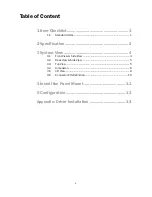
Page 6: ...tems 1 2 Specification 2 3 System View 4 3 1 Front View Side View 4 3 2 Rear View Side View 5 3 3 Top View 5 3 4 Dimension 6 3 5 I O View 9 3 6 Connector PIN Definition 10 4 Install the Panel Mount 11...

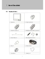
Page 7: ...1 1 Standard Items a System x 1 b Power connector x 1 c RS 232 connector x 2 d GPIO RS 232 422 485 connector x2 e Ground cable x 1 f Mounting bracket kit x 10 g Key x 2 h Rubber strip x 1 i Driver CD...

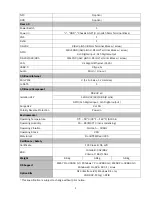
Page 8: ...uch Controller ETTI USB TPM Contoller NUVOTON TPM NPCT420 Watch Dog Timer Hardware WDT MB Dimension 185 x 120 mm IO Board Dimension 248 x 64 mm Expansion Mini PCIe 1 x miniPCIe half size LCD Touch Dis...

Page 9: ...2kV RS 232 x 2 1 x RS 232 422 485 8 pins GPIO 4ch Digital input 4ch Digital output Surge 3kV 2 x LAN Polarity Reverse Protection Power in Environmental Operating Temperature 0 oC 50 oC 32 oF 122 oF S...

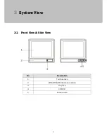
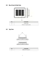
Page 10: ...4 3 System View 3 1 Front View Side View No Description 1 Touch screen 2 WIFI RFID NFC Antenna option 3 Key lock 4 USB 2 0 5 Power switch...

Page 11: ...5 3 2 Rear View Side View No Description 6 Cable clamp 7 Groove for mounting clip 3 3 Top View No Description 8 WIFI antenna option...

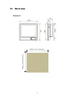
Page 12: ...6 3 4 Dimensions K746 12 1 300mm cut out dimension 280mm cut out dimension...

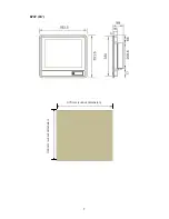
Page 13: ...7 K747 15 375mm cut out dimension 333mm cut out dimension...

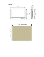
Page 14: ...8 K738 18 5 474mm cut out dimension 336mm cut out dimension...

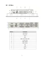
Page 15: ...9 3 5 I O View Number Description a Power switch b Power input c VGA d DVI D e COM6 RS 232 422 485 f 4 x DI 4 x DO g COM1 RS 232 h COM2 RS 232 i LAN j USB k Line out l Mic in...

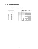
Page 16: ...on RS 232 422 485 mode changed by BIOS setting RS 232 Pin Define 1 DCD 2 DSR 3 RxD 4 RTS 5 TxD 6 CTS 7 DTR 8 GND RS 232 422 485 Pin Define RS 232 RS 422 RS 485 1 DCD TX DATA 2 DSR 3 RxD TX DATA 4 RTS...

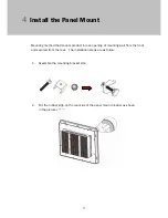
Page 17: ...s product into an opening of mounting wall from the front and secured from the rear The installation steps are as follow 1 Assemble the mounting bracket kits 2 Put the rubber strip on the rear side of...

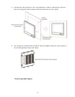
Page 18: ...5mm x 333mm from the front side of mounting wall with the sides of the front bezel shown on the outside 4 Use provided mounting bracket kits x10 to attach and tighten the panel mount product to the mo...

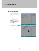
Page 19: ...em is booting up to enter the BIOS Setup utility 2 Select the Advanced tab 3 Select VGA COM Power Configuration Ports and press Enter to go to display the available options 4 To enable the power selec...

Page 20: ...ind every individual driver and utility that enables you to install the drivers in the Driver CD Please insert the Driver CD into the drive and double click on the index htm to pick the models You can...

Reviews: