18
Troubleshooting
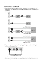
There are 26 ways to improperly connect two packs to a charger! After the
Start/Stop
button is
pressed, a special battery checking sequence automatically checks every wire before closing the
internal switches (if discharge wires are not used during charging). It is possible to get an unre-
lated safety code from a simple wiring issue.
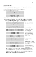
Operating errors appear as messages in the display. To determine the problem, look up the de-
scription below. Correct the error. If errors continue, contact FMA Customer Service.
Message
Problem
2 Pack Con. Err
Check pack wiring
Amps too low
Reset the charger
Bad EEPROM Write
Internal error
Bad FET supply voltage Check the input voltage
Bad Mode Number
Internal error
Bypass Overvolt
Check the pack wiring
C2 Pack Detected
Pack was added to Ch2 while charging
Cell < 0.1V
Low cell voltage
Ch1 Bad S. Count
Cell count cannot be determined; check for a cell < 0.5V
Ch1 has no Pack
Pack must be installed on Ch1
Ch1 No Add Up
Cell verification failed
Ch1 Pos < 0.5V
Check node wiring
Ch2 Bad S. Count
Cell count cannot be determined; check for a cell < 0.5V
Ch2 No Add Up
Cell verification failed
Charger Overcurrent
Make sure the charger current is steady
Check Pos. Term
Positive terminal not connected
Chg. Overvoltage
Cell is over voltage
Chgr Temp. >160F
Make sure the fan is working
Low Voltage Cell
Cell did not recover after 5 minutes of charge
Neg. Term. < 0V
Black banana jack is reading below 0 volts
No Plug Blocker
Plug Blocker required, but not installed
Node 10 < 0V
Last node wire is reading negative voltage
Reverse Polarity
Check wiring
Series Chrgrs?
Check that two chargers aren’t charging a series pack
Supply <10 Volts
Low input supply voltage
Supply >16 Volts
High input supply voltage
Supply Unstable
Possible thin supply wires; set input current limiting with Charge Control
Software
System Softstart
Check for good power supply leads
Temp out of Rnge
Make sure the fan is working


