background image

www.fmiproducts.com

125655-01B

17

PUREFIRE EMISSION CONTROL SYSTEM

This  fireplace  is  equipped  with  a  PureFire 

Emission  Control  System.  The  Catalytic 

Hood system reduces particulates emissions 

in a wood burning fireplace to meet the EPA 

Wood-Burning  Fireplace  Program  Phase  2 

emission level. 

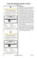
The EPA qualifying label, shown on page 18, 

will be affixed to the catalyst. Before lighting 

the first fire, remove and maintain this label in 

a safe place if needed for permits or building 

inspection. Prior to beginning installation, con

-

tact your local building official to determine the 

need to obtain a permit. For proper operation, 

catalyst must be replace every 3 to 5 years.

FUELING GUIDELINES

The fireplace grate must always be secured 

to the retaining brackets provided. The posi

-

tion of the grate must be centered against the 

back wall of the firebox.

Burn only dry, seasoned (cured) wood with 

less than 20% moisture. Avoid the use of 

treated, painted and laminated wood. Never 

burn garbage or other foreign materials. Do 

not use artificial logs, colored newspaper or 

petroleum based fire starters. Avoid wood with 

high salt content. All of these materials may 

contain compounds which can shorten the 

life of the catalyst. Wet or unseasoned wood 

may lower catalytic temperatures and result 

in inefficient operation. 
The catalyst is designed to function at opti

-

mum efficiency when the fireplace is burning 

clean,  dry,  cord  wood  as  fireplace  fuel. A 

simple visual inspection of the chimney dur-

ing the wood burning process will determine 

catalyst performance. 

The  fuel  load  should  always  be  placed  on 

the back of the grate. Use clean dry wood, 

seasoned cord wood is the best choice. 

Never burn trash, plastics, gasoline, rubber, 

industrial solvents, flammable liquids, naptha, 

household garbage, material treated with 

petroleum products, leaves, paper products, 

cardboard or salt driftwood. 

Refer to your FMI PRODUCTS, LLC 

Home-

owner's Guide 

included with your fireplace for 

proper fire building technique and ash removal 

procedures. These fueling guidelines must be 

followed in order to achieve maximum emis-

sions performance from the PureFire System.

OPERATION

The proper use of a wood burning fireplace 

equipped  with  the  catalyst  will  significantly 

reduce the emissions that it produces. Simple 

fuel considerations with regard to moisture 

content, size, and quality of fuel will help 

control the production of wood smoke and 

improve the performance of the catalyst and 

fireplace  efficiency.  With  proper  care,  the 

catalyst will provide years of fuel savings 

and lowered emissions. By following some 

simple guidelines, you will ensure maximum 

performance and longevity.

The smoke that is usually seen coming out 

of a chimney is essentially a combination of 

unburned fuel (carbon and hydrogen) and 

moisture in the form of water vapor. The cata

-

lyst is a technology that provides secondary 

combustion for the wood burning process. 

MAINTENANCE

The PureFire System is a maintenance free 

technology. Do not attempt to remove or clean 

the combustor. The direct flame from the fire 

will  clean  the  combustor.  Only  a  certified 

technician should remove the unit. To ensure 

proper fireplace operation, the PureFire Sys

-

tem should be replaced every 3 to 5 years 

(see 

Parts

 on page 20). 

NOTE: Chimney smoke may be visible during 

the first 8 to 10 minutes of fireplace operation 

when the fire is first getting started and the 

final 8 to 10 minutes of operation while the fire 

is dissipating. Under normal operating condi

-

tions, you should see little or no smoke coming 

out  of  the  chimney.  If  continuous  smoke  is 

visible, make sure only dry seasoned wood 

is being burned. If visible smoke continues,  

the combustor has ceased to function or there 

is thermal crumbling. Call FMI PRODUCTS, 

LLC at 1-866-328-4537 for replacement parts. 


Summary of Contents for GCAT42/50A

Page 1: ...install and maintain your appliance it also contains information that will enable you to obtain re placement parts or accessory items when needed Keep it with your other important papers This firepla...

Page 2: ...llation of the fireplace read these instructions through completely ThisFMIPRODUCTS LLCfireplaceandits componentsaresafewheninstalledaccord ing to this installation manual Unless you use FMI PRODUCTS...

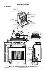
Page 3: ...COMBUSTIBLE MATERIAL ON FACE MINIMUM 18 TO PERPENDICULAR SIDEWALL HEARTH EXTENSION 66 X 20 2 CHIMNEY AIRSPACE CLEARANCE TO COMBUSTIBLE MATERIAL 42 23 1 2 25 1 8 22 3 4 30 1 2 29 4 3 8 15 3 4 5 8 17 5...

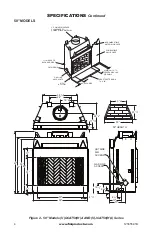
Page 4: ...O COMBUSTIBLE MATERIAL COMBUSTIBLE WALL BOARD NO COMBUSTIBLE MATERIAL ON FACE 0 TO BOTTOM OUTSIDE AIR 11 2 AIR SPACE BACK AND SIDES GAS LINE KNOCKOUTS 12 EACH SIDE MINIMUM 18 TO PERPENDICULAR SIDEWALL...

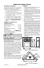
Page 5: ...Consider a location where fireplace will not be affected by drafts air conditioning ducts windows or doors 3 A location that avoids cutting of joists or roof rafters will make installation easier 4 An...

Page 6: ...arth extension from shifting and seal gap between fireplace frame and hearth extension with a noncombustible material see Figure 5 WARNING Hearthextension is to be installed only as shown in Figure 4...

Page 7: ...ons Figure 7 Outside Air Kit Secure to Collars with Metal Tape Screws or Straps Min of 1 4 x 20 in size Air Inlet Location Must Allow For Bushes or Snow Vent Hood Required for Wall Installation Air In...

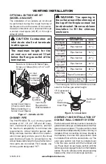
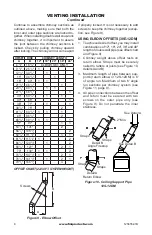
Page 8: ...pipe sections are locked to gether When installing double wall snap lock chimney together it is important to assure the joint between the chimney sections is locked Check by pulling chimney upward af...

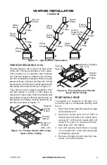
Page 9: ...igure 13 Firestop Spacer with Attic Space Above Ceiling Existing Ceiling Frame Firestop Spacer Screws or Staples Min of 8 Firestop Spacer Screws or Staples Min of 8 PENETRATING ROOF To maintain a 2 cl...

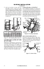
Page 10: ...12F 10DM Determine the flashing to be used with the roof opening chart Slide flashing over pipe until base is flat against roof Replace as many shingles as needed to cover exposed area and flashing ba...

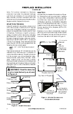
Page 11: ...2 Min 10 3 Min 2 Min 3 Min Level of Flue Gas Outlet Figure 19 18 Foot Rule Terminations Spark Arrestor The fireplace system must be terminated with the listed round top or chase terminations In any ca...

Page 12: ...ey should be positioned a distance apart as shown in Figure 20 4 Install rear refractory panel This panel has a top and bottom To determine which is which match up the pattern on the rear panel with t...

Page 13: ...la tion from gas line conduit sleeve Save insulation for reuse Replace screws 3 Run a 1 2 black iron gas line into fireplace through the rear at gas line conduit sleeve if usingaraisedplatform addheig...

Page 14: ...g Fireplaces ANS Z21 60 or Z21 84 and shall also be installed in accordance with the National Fuel Gas Code ANSI 7223NFPA 54 latest edition If you wish to install an unvented vent free gas log set onl...

Page 15: ...si tion making sure top pins slide into door track Door is installed when top door pin snaps into spring clip 2 Repeat step 1 for remaining door If you find doors do not close properly or do not appea...

Page 16: ...built or if combustion air gate is not completely open The following tips should be followed to assure that both the fireplace and glass door retain their beauty and function properly Both the flue d...

Page 17: ...d with petroleum products leaves paper products cardboard or salt driftwood Refer to your FMI PRODUCTS LLC Home owner s Guide included with your fireplace for proper fire building technique and ash re...

Page 18: ...els that have not met this emissions level Exposure to smoke has been associated with respiratory illness and other health problems Models that have lower smoke emissions may reduce your risk PHASE 2...

Page 19: ...LACEMENT PARTS If this product is missing a part or has a broken component please do not return it to the store Call FMI PRODUCTS LLC at 1 866 328 4537 to answer questions and replace parts under warr...

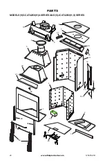
Page 20: ...www fmiproducts com 125655 01B 20 PARTS MODELS V GCAT42 50 H A SERIES AND V JCAT42 50 H S SERIES 1 21 20 5 6 7 10 9 11 12 13 16 17 15 14 8 24 23 3 25 18 2 22 19 4 26 27 28 29 30...

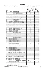
Page 21: ...sh Box Assembly 1 20 Inner Dome Assembly 1 21 Smoke Shield 1 22 Damper Control Bracket 1 23 109457 02 Screen 42 2 109457 01 Screen 50 2 117556 02 Screen 42 Stainless 2 117556 01 Screen 50 Stainless 2...

Page 22: ...www fmiproducts com 125655 01B 22 PARTS MODELS V GCAT50 H A SERIES AND V JCAT50 H S A SERIES Picture may vary from actual 1 2 5 3 4 6 6...

Page 23: ...1 Left Stacked 42 Natural White 1 125836 02 Left Herringbone 42 Red 1 125836 01 Left Herringbone 42 Natural White 1 125839 02 Left Stacked 50 Red 1 125839 01 Left Stacked 50 Natural White 1 125842 02...

Page 24: ...BDG42B 42 Brushed Brass BD50 50 Black BD50P 50 Platinum BD50B 50 Brushed Brass DOUBLE WALL PIPE 12 12DM 18 12DM 24 12DM 36 12DM 48 12DM 12 12HT 18 12HT 24 12HT 36 12HT and 48 12HT 30 OFFSET AND RETUR...

Page 25: ...6 12 Pitch V12F 10DM 6 12 to 12 12 Pitch ACCESSORIES Continued SQUARE CHASE TOP TERMINATION STL 12D AND STL 12DMP BLACK ROUND TOP TERMINATIONS RLT 12D AND RLT 12HT STORM COLLAR SC2 1 FIRESTOP SPACER...

Page 26: ...______________________________ ______________________________________________________ ______________________________________________________ ______________________________________________________ ____...

Page 27: ...______________________________ ______________________________________________________ ______________________________________________________ ______________________________________________________ ____...

Page 28: ...125655 01 Rev B 07 12 2701 S Harbor Blvd Santa Ana CA 92704 1 866 328 4537 www fmiproducts com...

Reviews: