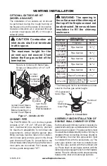
background image

www.fmiproducts.com

125655-01B

5

FIREPLACE INSTALLATION

FRAMING

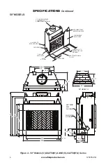
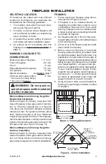
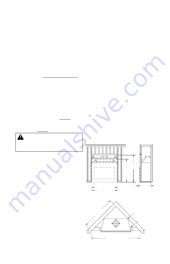
1.  Frame opening for fireplace using dimen

-

sions shown in Figures 3 and 4.

2.  If  fireplace  is  to  be  installed  directly  on 

carpeting, tile (other than ceramic) or any 

combustible material other than wood 

flooring, fireplace must be installed upon 

a metal or wood panel extending full width 

and depth of fireplace.

3.  Set fireplace directly in front of this open

-

ing and slide unit back until nailing flanges 

touch side framing.

4.  Check level of the fireplace and shim with 

sheet metal if necessary.

5.  Before securing fireplace to prepared 

framing, ember protector (provided) must 

be placed between hearth extension (not 

supplied) and under bottom front edge of 

fireplace to protect against glowing embers 

falling through. If fireplace is to be installed 

on a raised platform, a Z-type ember pro-

tector (not supplied) must be fabricated to 

fit  your  required  platform  height.  Ember 

protector should extend under fireplace a 

minimum of 1 

1

/

2

". Ember protector should 

be made of galvanized sheet metal (28 

gauge minimum to prevent corrosion.

6.  Using screws or nails, secure fireplace to 

framing through flanges located on sides 

of fireplace.

Figure 3 - Framing Dimensions

Figure 4 - Corner Installation

SELECTING LOCATION

To  determine  the  safest  and  most  efficient 

location for the fireplace, you must take into 

consideration the following guidelines:

1.  The location must allow for proper clear

-

ances (see Figures 5 and 6).

2.  Consider a location where fireplace will 

not be affected by drafts, air conditioning 

ducts, windows or doors.

3.  A location that avoids cutting of joists or 

roof rafters will make installation easier.

4.  An outside air kit is available with this 

fireplace (see 

Optional Outside Air Kit

 on 

page 7).

MINIMUM CLEARANCE TO 

COMBUSTIBLES

Back and sides of fireplace 

1

/

2

" min.*

Front of fireplace 

48" min.

Floor** 

0" min.

Perpendicular wall to opening 

18" min.

Top spacers 

0" min.

Mantel clearances 

see 

Mantels

, page 7

Chimney outer pipe surface 

2" min.

* Not required at nailing flanges
** See step 2 of 

Framing

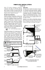
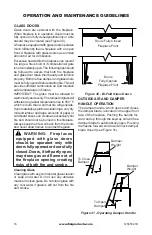
 WARNING: Do not pack re

-

quired air spaces with insulation 

or other materials.

Minimum/Maximum Chimney Height for 

Residential Installation

Minimum height of chimney, measured from 

base of fireplace to flue gas outlet of termina

-

tion, is 16 feet for straight flue or a flue with 

one elbow set. Maximum distance between 

elbows is 6 feet. For systems with two elbow 

sets,  minimum  height  is  22  feet.  Maximum 

height of any system is 50 feet. This measure

-

ment includes fireplace, chimney sections and 

height of termination assembly at level of the 

flue gas outlet (see Figure 16, page 10).

Minimum/Maximum Chimney Height for 

Outdoor Installation

Minimum height of chimney, measured from 

base of fireplace to flue gas outlet of termina

-

tion, is 9.5 feet (minimum of 4 feet of chimney 

pipe sections required for outdoor installation).

71" (50" Models)

100" (50" Models)

65" (42" Models)

92" (42" Models)

86.5" (36" Models)

61" (36" Models)

Maintain 1 

1

/

2

"

Clearance 

at Sides and 

Back of Fireplace

1

/

2

" Clearance

Not Required at 

Nailing Flanges 

30.125"

59" (50" Models)

58.125"

67.125"

51.25" (42" Models)

45.25" (36" Models)

28.250" (36" Models)

Summary of Contents for GCAT42/50A

Page 1: ...install and maintain your appliance it also contains information that will enable you to obtain re placement parts or accessory items when needed Keep it with your other important papers This firepla...

Page 2: ...llation of the fireplace read these instructions through completely ThisFMIPRODUCTS LLCfireplaceandits componentsaresafewheninstalledaccord ing to this installation manual Unless you use FMI PRODUCTS...

Page 3: ...COMBUSTIBLE MATERIAL ON FACE MINIMUM 18 TO PERPENDICULAR SIDEWALL HEARTH EXTENSION 66 X 20 2 CHIMNEY AIRSPACE CLEARANCE TO COMBUSTIBLE MATERIAL 42 23 1 2 25 1 8 22 3 4 30 1 2 29 4 3 8 15 3 4 5 8 17 5...

Page 4: ...O COMBUSTIBLE MATERIAL COMBUSTIBLE WALL BOARD NO COMBUSTIBLE MATERIAL ON FACE 0 TO BOTTOM OUTSIDE AIR 11 2 AIR SPACE BACK AND SIDES GAS LINE KNOCKOUTS 12 EACH SIDE MINIMUM 18 TO PERPENDICULAR SIDEWALL...

Page 5: ...Consider a location where fireplace will not be affected by drafts air conditioning ducts windows or doors 3 A location that avoids cutting of joists or roof rafters will make installation easier 4 An...

Page 6: ...arth extension from shifting and seal gap between fireplace frame and hearth extension with a noncombustible material see Figure 5 WARNING Hearthextension is to be installed only as shown in Figure 4...

Page 7: ...ons Figure 7 Outside Air Kit Secure to Collars with Metal Tape Screws or Straps Min of 1 4 x 20 in size Air Inlet Location Must Allow For Bushes or Snow Vent Hood Required for Wall Installation Air In...

Page 8: ...pipe sections are locked to gether When installing double wall snap lock chimney together it is important to assure the joint between the chimney sections is locked Check by pulling chimney upward af...

Page 9: ...igure 13 Firestop Spacer with Attic Space Above Ceiling Existing Ceiling Frame Firestop Spacer Screws or Staples Min of 8 Firestop Spacer Screws or Staples Min of 8 PENETRATING ROOF To maintain a 2 cl...

Page 10: ...12F 10DM Determine the flashing to be used with the roof opening chart Slide flashing over pipe until base is flat against roof Replace as many shingles as needed to cover exposed area and flashing ba...

Page 11: ...2 Min 10 3 Min 2 Min 3 Min Level of Flue Gas Outlet Figure 19 18 Foot Rule Terminations Spark Arrestor The fireplace system must be terminated with the listed round top or chase terminations In any ca...

Page 12: ...ey should be positioned a distance apart as shown in Figure 20 4 Install rear refractory panel This panel has a top and bottom To determine which is which match up the pattern on the rear panel with t...

Page 13: ...la tion from gas line conduit sleeve Save insulation for reuse Replace screws 3 Run a 1 2 black iron gas line into fireplace through the rear at gas line conduit sleeve if usingaraisedplatform addheig...

Page 14: ...g Fireplaces ANS Z21 60 or Z21 84 and shall also be installed in accordance with the National Fuel Gas Code ANSI 7223NFPA 54 latest edition If you wish to install an unvented vent free gas log set onl...

Page 15: ...si tion making sure top pins slide into door track Door is installed when top door pin snaps into spring clip 2 Repeat step 1 for remaining door If you find doors do not close properly or do not appea...

Page 16: ...built or if combustion air gate is not completely open The following tips should be followed to assure that both the fireplace and glass door retain their beauty and function properly Both the flue d...

Page 17: ...d with petroleum products leaves paper products cardboard or salt driftwood Refer to your FMI PRODUCTS LLC Home owner s Guide included with your fireplace for proper fire building technique and ash re...

Page 18: ...els that have not met this emissions level Exposure to smoke has been associated with respiratory illness and other health problems Models that have lower smoke emissions may reduce your risk PHASE 2...

Page 19: ...LACEMENT PARTS If this product is missing a part or has a broken component please do not return it to the store Call FMI PRODUCTS LLC at 1 866 328 4537 to answer questions and replace parts under warr...

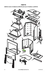
Page 20: ...www fmiproducts com 125655 01B 20 PARTS MODELS V GCAT42 50 H A SERIES AND V JCAT42 50 H S SERIES 1 21 20 5 6 7 10 9 11 12 13 16 17 15 14 8 24 23 3 25 18 2 22 19 4 26 27 28 29 30...

Page 21: ...sh Box Assembly 1 20 Inner Dome Assembly 1 21 Smoke Shield 1 22 Damper Control Bracket 1 23 109457 02 Screen 42 2 109457 01 Screen 50 2 117556 02 Screen 42 Stainless 2 117556 01 Screen 50 Stainless 2...

Page 22: ...www fmiproducts com 125655 01B 22 PARTS MODELS V GCAT50 H A SERIES AND V JCAT50 H S A SERIES Picture may vary from actual 1 2 5 3 4 6 6...

Page 23: ...1 Left Stacked 42 Natural White 1 125836 02 Left Herringbone 42 Red 1 125836 01 Left Herringbone 42 Natural White 1 125839 02 Left Stacked 50 Red 1 125839 01 Left Stacked 50 Natural White 1 125842 02...

Page 24: ...BDG42B 42 Brushed Brass BD50 50 Black BD50P 50 Platinum BD50B 50 Brushed Brass DOUBLE WALL PIPE 12 12DM 18 12DM 24 12DM 36 12DM 48 12DM 12 12HT 18 12HT 24 12HT 36 12HT and 48 12HT 30 OFFSET AND RETUR...

Page 25: ...6 12 Pitch V12F 10DM 6 12 to 12 12 Pitch ACCESSORIES Continued SQUARE CHASE TOP TERMINATION STL 12D AND STL 12DMP BLACK ROUND TOP TERMINATIONS RLT 12D AND RLT 12HT STORM COLLAR SC2 1 FIRESTOP SPACER...

Page 26: ...______________________________ ______________________________________________________ ______________________________________________________ ______________________________________________________ ____...

Page 27: ...______________________________ ______________________________________________________ ______________________________________________________ ______________________________________________________ ____...

Page 28: ...125655 01 Rev B 07 12 2701 S Harbor Blvd Santa Ana CA 92704 1 866 328 4537 www fmiproducts com...

Reviews: