background image

www.fmiproducts.com

125883-01C

7

INSTALLATION

Continued

CHECKING GAS CONNECTIONS

 WARNING: Test all gas piping and connec-

tions, internal and external to unit, for leaks 

after installing or servicing. Correct all leaks 

at once.

  WARNING:  Never  use  an  open  flame  to 

check for a leak. Apply a noncorrosive leak 

detection fluid to all joints. Bubbles forming 

show a leak. Correct all leaks at once.

 CAUTION: Make sure external regulator has 

been installed between propane/LP supply and 

appliance. See guidelines under 

Connecting 

to Gas Supply

, page 6.

PRESSURE TESTING GAS SUPPLY PIPING 

SYSTEM 

Test Pressures In Excess Of 1/2 PSIG (3.5 

kPa)

1. Disconnect appliance with its appliance main gas 

valve (control valve) and equipment shutoff valve 

from gas supply piping system. Pressures in ex-

cess of 1/2 psig will damage appliance regulator.

2. Cap off open end of gas pipe where equipment 

shutoff valve was connected.

3. Pressurize supply piping system by either open-

ing propane/LP supply tank valve for propane/LP 

gas or opening main gas valve located on or near 

gas meter for natural gas or using compressed 

air.

4. Check all joints of gas supply piping system. Ap-

ply noncorrosive leak detection fluid to all joints. 

Bubbles forming show a leak. 

5. Correct all leaks at once.

6. Reconnect  appliance  and  equipment  shutoff 

valve to gas supply. Check reconnected fittings 

for leaks. 

Test Pressures Equal To or Less Than 1/2 PSIG 

(3.5 kPa)

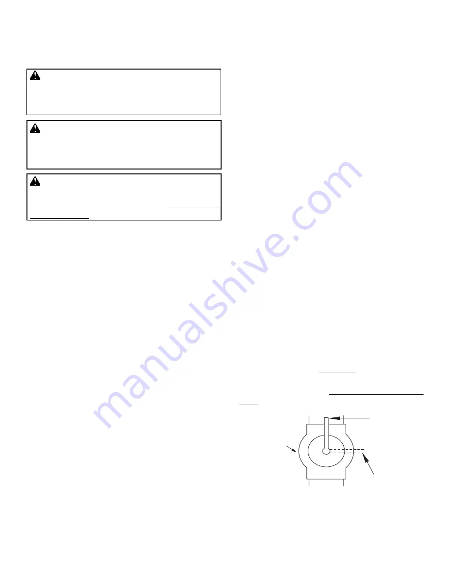
1. Close equipment shutoff valve (see Figure 4).

2. Pressurize supply piping system by either open-

ing propane/LP supply tank valve for propane/LP 

gas or opening main gas valve located on or near 

gas meter for natural gas or using compressed 

air.

3. Check all joints from gas meter to equipment 

shutoff valve for natural gas or propane/LP 

supply to equipment shutoff valve for propane/

LP. Apply noncorrosive leak detection fluid to all 

joints. Bubbles forming show a leak. 

4. Correct all leaks at once.

PRESSURE TESTING APPLIANCE GAS 

CONNECTIONS

1. 

Open equipment shutoff valve (see Figure 4).

2. Open main gas valve located on or near gas 

meter for natural gas or open propane/LP supply 

tank valve.

3. Make sure control knob of appliance is in the 

OFF position.

4. Check  all  joints  from  gas  meter  to  equipment 

shutoff valve for natural gas or propane/LP supply 

to equipment shutoff valve for propane/LP. Ap

-

ply noncorrosive leak detection fluid to all joints. 

Bubbles forming show a leak. 

5. Correct all leaks at once.

6. Light appliance (see 

Operation

, page 15). Check 

all other internal joints for leaks.

7. Turn off appliance (see 

To Turn Off Gas to Appli-

ance

, page 15).

Figure 4 - Equipment Shutoff Valve

Open

Closed

Equipment 

Shutoff 

Valve

Summary of Contents for MM2FR

Page 1: ...lammable vapors and liquids in the vicinity of this or any other appliance An LP cylinder not connected for use shall not be stored in the vicinity of this or any other appliance WARNING For Outdoor Use Only CARBON MONOXIDE WARNING This appliance can pro duce carbon monoxide which has no odor Using it in an enclosed space can kill you Never use this appliance in an enclosed space suchasacamper ten...

Page 2: ...tended Solid fuels shall not be burned in this appliance This appliance is only for use with the type of gas indicated on the rating plate This ap pliance is not convertible for use with other gases WARNING This product contains and or generates chemicals known to the state of California to cause cancer or birth defects or other reproductive harm IMPORTANT Read this owner s manual care fullyandcom...

Page 3: ...m and any gas control which has been un der water 8 Turn appliance off and let cool before servicing installing or repairing Only a qualified service person should install service or repair appliance 9 This appliances must not be connected to any external electrical source 10 Operating appliance above elevations of 4 500 feet may cause pilot outage 17 To prevent performance problems do not use pro...

Page 4: ... 96 000 Btu hr Gas Type Natural Gas Only Ignition Manual Manifold Pressure 6 0 w c Minimum Inlet Supply Pressure 7 0 w c Maximum Inlet Supply Pressure 10 5 w c Orifice 12 MMFRBPB MMFRBPS Rating 95 000 Btu hr Gas Type Propane LP Gas Only Ignition Manual Manifold Pressure 10 5 w c Minimum Inlet Supply Pressure 11 w c Maximum Inlet Supply Pressure 14 w c Orifice 33 ...

Page 5: ...cal codes CAUTION Never connect propane LP fire ring directly to the propane LP supply This appliance requires an external regulator not supplied Install the external regulator be tween the appliance and propane LP supply WARNING Never connect natural gas fire ring to private non utility gas wells This gas is commonly known as wellhead gas Installation Items Needed Before installing appliance make...

Page 6: ...p within reach for test gauge hook up NPT tap must be upstream from appliance see Figure 3 IMPORTANT Install equipment shutoff valve in an accessible location The equipment shutoff valve is for turning on or shutting off the gas to the appliance Check your building codes for any special require ments for locating equipment shutoff valve to fire places Apply pipe joint sealant lightly to male NPT t...

Page 7: ...w a leak 5 Correct all leaks at once 6 Reconnect appliance and equipment shutoff valve to gas supply Check reconnected fittings for leaks Test Pressures Equal To or Less Than 1 2 PSIG 3 5 kPa 1 Close equipment shutoff valve see Figure 4 2 Pressurize supply piping system by either open ing propane LP supply tank valve for propane LP gas or opening main gas valve located on or near gas meter for nat...

Page 8: ...to the gas regulator using a 1 2 flared flex line not included There is a 1 hole in the heat shield for the gas line See Figure 5 Figure 5 Gas Line Planning 1 Hole Heat Shield 1 2 Flare Connector 1 Locate a flat even surface to build your fire ring See Specifications page 4 for sizing and Minimum Clearances page 5 when selecting a location 2 Use 8 blocks to build the first layer See Figure 6 After...

Page 9: ...vel verify all the blocks are level Shim if necessary 4 When starting the top layer stagger blocks to the layer below Use 7 full blocks and one half block to build the top layer see Figure 9 After laying out all blocks using a level verify all the blocks are level Shim if necessary 5 Place 4 heat shield retaining brackets longer of the 2 types of brackets included with the MMFRB Series burner syst...

Page 10: ...taining brackets shorter of the 2 types of brackets included with the MMFRB Series burner system on the top layer of blocks in the pattern shown in Figure 13 Heat Shield Burner Retaining Brackets 9 Connect incoming gas line to regulator shown in Figure 5 page 8 before placing burner system into place 10 Place burner system on the retainer brackets in the center of the fire ring with the controls g...

Page 11: ...em in two boxes each weighing around 42 pounds Lava rocks range in size Begin by placing the smaller rocks between the burner tubes filling the whole pan in a single layer of rocks Avoid placing rocks on the pilot shield They will obstruct the view of the pilot when you go to light the pilot You may want to light the pilot first before adding the lava rock see Lighting Instructions page 12 Place l...

Page 12: ...FF PULL PUSH FROM PILOT POSITION SLIGHT PUSH TO TURN OFF PULL PUSH ON OFF On Off OFF OFF Figure 19 Thermocouple and Pilot Control Knob 5 Turn control knob counterclockwise to the PILOT position and press in Keep control knob pressed in for five 5 seconds Note You may be running this fire ring for the first time after hooking up to gas supply If so the control knob may need to be pressed in for 30 ...

Page 13: ...cation of the Pilot Adjustment Screw Thermocouple Pilot Check pilot flame pattern and burner flame patterns often PILOT ASSEMBLY The pilot assembly is factory preset for proper flame height Alterations may have occurred during ship ping and handling The pilot is located underneath the pilot shield on the burner pan The thermocouple should be fully enveloped in flame The flame should not be lifting...

Page 14: ... follow directions on the can you could damage the pilot assembly 1 Shut off unit including pilot Allow unit to cool for at least thirty minutes 2 Inspect burner pilot and primary air inlet holes on injector holder for dust and dirt see Figure 22 3 Blow air through the ports slots and holes in the burner 4 Check injector holder located at end of burner tube again Remove any large particles of dust...

Page 15: ...talled 5 Pilot adjustment screw closed 6 Pilot is clogged 7 Low gas pressure REMEDY 1 Reconnect ignitor cable 2 Free ignitor cable if pinched by any metal or tubing Keep ignitor cable dry 3 Replace ignitor cable 4 Replace ignitor 5 Replace pilot assembly 6 Replace pilot assembly 7 Install new alkaline battery in electronic ignitor Verify battery is installed correctly 1 Turn on gas supply or open ...

Page 16: ...proper burner orifice size REMEDY 1 Press in control knob fully 2 After pilot lights keep control knob pressed in 30 seconds 3 Fully open equipment shut off valve 4 A Contact local natural or propane LP gas company B Clean pilot see Cleaning and Maintenance page 14 or replace pilot assembly 5 Hand tighten until snug then tighten 1 4 turn more 6 Replace thermocouple 7 Replace control valve 1 Contac...

Page 17: ... OBSERVED PROBLEM Burner is excessively noisy Note Themovementandcom bustion of gas will create low unavoidable levels of noise Gas odor even when control knob is in OFF position Gas odor during combustion Fire ring produces a clicking ticking noise just after burner is lit or shuts off WARNING If you smell gas Shut off gas supply Do not try to light any appliance Do not touch any electrical switc...

Page 18: ...www fmiproducts com 125883 01C 18 PARTS BURNER MODELS MMFRBNB MMFRBPB MMFRBNS MMFRBPS 3 5 16 2 15 21 22 13 20 23 18 26 19 8 6 4 17 24 25 10 7 9 11 14 14 1 12 ...

Page 19: ...01072 01 Ignitor Wire Harness 1 7 901069 01 Pilot NG 1 901069 02 Pilot LP 1 8 116786 01 Male Fitting 1 9 901082 01 Regulator NG 1 901082 02 Regulator LP 1 10 901062 01 Brass Elbow 1 11 901068 02 Manual Valve 1 12 14399 Brass Elbow 1 13 125897 01 Valve Bracket 1 125897 02 Valve Bracket 1 14 111435 01 Electronic Ignitor 1 15 901079 01 Control Knob 1 16 11209 Nut 10 24 Hex 2 17 119795 01 Venturi Gask...

Page 20: ...2FRL QUANITY 15 MM3FRL QUANITY 23 HALF BLOCK 125869 01 MM2FR MM3FR QUANITY 1 126372 01 MM2FRL MM3FRL QUANITY 1 BLOCK COVER 125957 03 MM2FR MM3FR QUANITY 1 MM2FRL MM3FRL QUANITY 1 ACCESS DOOR INCLUDING RING NUT WASHER 125888 01 MM2FR MM3FR QUANITY 1 ACCESS DOOR INCLUDING RING NUT WASHER LEDGE STONE 125888 02 MM2FRL MM3FRL QUANITY 1 DOOR HANDLE ASSY 111454 02 MM2FR MM3FR QUANITY 1 MM2FRL MM3FRL QUAN...

Page 21: ...chase date Usually we will ask you to return the part to the factory SERVICE HINTS When Gas Pressure Is Too Low pilot will not stay lit burners will have delayed ignition appliance will not produce specified heat propane LP gas supply may be low You may feel your gas pressure is too low If so contact your local propane LP or natural gas supplier TECHNICAL SERVICE You may have further questions abo...

Page 22: ...____________ ___________________________________________________________________ ___________________________________________________________________ ___________________________________________________________________ ___________________________________________________________________ ___________________________________________________________________ _______________________________________________...

Page 23: ...____________ ___________________________________________________________________ ___________________________________________________________________ ___________________________________________________________________ ___________________________________________________________________ ___________________________________________________________________ _______________________________________________...

Page 24: ...ough authorized dealers of this product and or FMI PRODUCTS LLC who will provide original factory replacement parts Failure to use original factory replacement parts voids this warranty Travel handling transportation diagnostic material labor and incidental costs associated with warranty repairs unless expressly covered by this warranty are not reimbursable under this warranty and are the responsi...

Reviews: