9
EN
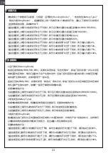
This function is used to protect the safety of the model and the operator when the receiver cannot
normally receive the signal from the transmitter and is out of control. The receiver defaults that the
throttle channel is fixed to be out of control and enters the brake state. After other channels are out
of control, the receiver has no signal output. If you set it on the transmitter, it will output according to
the set value.
Attention:
• Make sure the product is installed and calibrated correctly, failure to do so may result in serious
injury.
• Please carefully check each power device and car frame instructions to ensure the power matching
is reasonable before use. Avoid damaging power system due to incorrect matching.
• Do not let the external temperature of the system exceed 90°C /194°F , because high temperature
will damage the power system.
• Make sure the receiver's battery is disconnected before turning off the transmitter, failure to do so
may lead to unintended operation or loss of control.
• After use, remember to disconnect the battery and the ESC. If the battery isn't disconnected, the
ESC will consume electric energy all the time even if it is off. It will discharge completely if connect
the battery for a long time, thus resulting in the failure of the battery or the ESC. We are not
responsible for any damage caused by this!
• Make sure the receiver is mounted away from motors or any device that emits excessive electrical
noise.
• Keep the antenna of the receiver at least 1cm away from conductive materials such as carbon or
metal.
• Do not power on the receiver during the setup process to prevent loss of control.
Failsafe
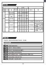
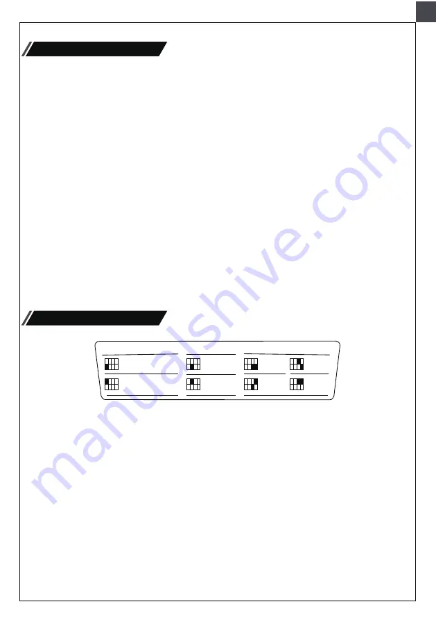
ESC Parameter Setting
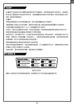
Dial Switch sign
Running Mode
FWD/REV/BRK
FWD/REV
Lipo
NiMH
0%
50%
75%
100%
Battery Type Drag Brake
Setting Method:
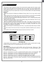
There are three parameters can be set for the ESC, which are "Running mode", "Battery type", "Drag
brake", There are slide switches numbered 1 2 3 4 on the radio panel . The above parameters can be
set by dialing down and up.
The specific operation is as follows:
The Dial Switch on the transmitter is used to set ESC parameters, that is, the Dial Switch is located
at different positions and the corresponding parameter values are different.
When No. 1 slide switch is on the down, it indicates that the operation mode is set to FWD / REV / BRK.
When No. 1 slide switch is on the up, it indicates that the operation mode is set to FWD/REV.
When No. 2 slide switch is on the down, it indicates that the battery type is set to Lipo.
When No. 2 slide switch is on the up, it indicates that the battery type is set to NiMH.
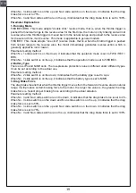
When No. 3 and No.4 slide switch are on the down, it indicates that the drag brake force is set to 0%.
When No. 3 slide switch is on the down and No.4 slide switch is on the up, it indicates that the drag
brake force is set to 50%.
Summary of Contents for 1:12 TOYOTA FJ45 Pick-up
Page 14: ...14 CN 14 14 3 MADE IN CHINA 14 FMS...
Page 15: ...15 CN 1 2 3 4 2 4GHz...
Page 19: ...19 CN 1S 110 C 70 C G LED BIND 1 1 2 LED 1 10s 2 1 OFF M M 3Pin S 2 a 3 b 0 c d...
Page 22: ...22 CN CH4 I II III IV V 3 1 0 5 0 5 3 1 0 5 0 5...
Page 23: ...AAA 1 2 4 AAA 3 4 2V LED 23 CN 1 2 1 Bind 2 3 1 2 OFF 1 USB 2 LED LED 3 4...
Page 24: ...24 CN 1 USB 2 1 2 3...
Page 26: ...26 CN CN 1 2 EN Rearview mirror installation EN Removable Roof...
Page 28: ...28 EN Finished Frame Sets CN C1375 C1367 C1368...
Page 29: ...29 C1367 C1372 C1338 C1379 C1349 C1382 C1369 C1367...
Page 32: ...EN Center Transmission Gear Box Assembly CN EN Main Gear Box Assembly CN 32 C1363 C1363...
Page 33: ...33 EN Hard Body Set CN C1360 C1346 C1348 V C1348 C1352 C1352 C1355 C1354 C1350...
Page 35: ...35 EN Hopper CN C1361 C1357 C1358 C1341 C1348 C1356 C1356...

