Operating Manual BKS015
26.11.2018
5
2
System Description
2.1
Functional Description
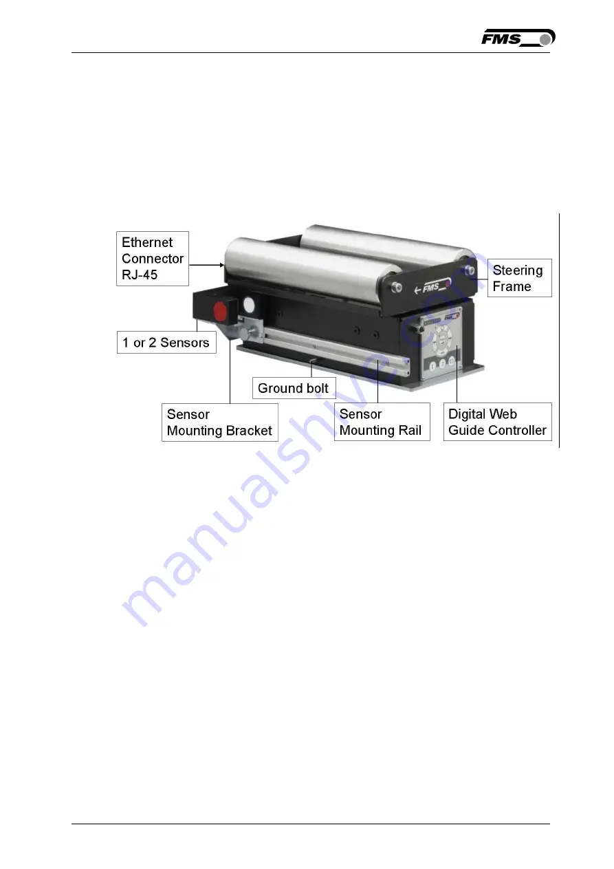
Figure 1 shows the BKS015 web guiding system with its basic components.
The sensors measure the position of the web edge and send this information as an
analogue signal to the built-in web guide controller unit. The control compares the
position feedback signal with the reference. If the difference of these two values is
higher then the stored dead band value, the steering frame will be adjusted.
Fig. 1: Basic BKS015.EIP system
K015006e
2.2
Steering Frame
The steering frame consists of a fixed lower and a moveable upper frame that
supports the rollers. The upper frame is activated by a stepper motor. The rollers
are manufactured and balanced according to customer specification. End positions
are controlled by hall sensors. The material sensors are mounted on the lower
frame by means of a bracket array and are easily adjustable to the web width.
2.3
Web Guide Controller
The micro-processor based electronic control unit handles all calculations and
communications tasks. Three buttons and a five key wind-rose serve as the man-
machine interface. Parameter setting can be performed via the front panel or
through a Web Browser (IE 7.0 or higher) or via the EtherNet/IP.
2.4
Sensors
Optical sensors (AZS04) and ultrasonic sensors (US01B) are available from FMS to
work in conjunction with the BKS015.EIP system. These sensors provide a signal of
0...10V. With them edge and center applications can be covered. A wide range of


