Operating Manual EMGZ470A/472A
18
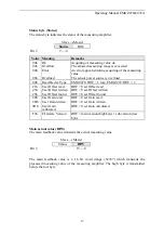
9
Calibrating the Measuring Amplifier
To get correct measuring values, offset and gain have to be determinate when putting
the device into operation. There are several methods for this task:
Method
Use with
Advantage
Simulating method
calibration within the PLC
Module 1+2 No settings required for the
measuring amplifier
Simulating method
calibration using initial
parameters
Module 1+2 Can be done without programming
Simulating method
calibration using control byte
Module 1
Highest flexibility
Mathematical method
Module 1
Less accurate than simulating
method
9.1
Simulating Method, Calibration within the PLC
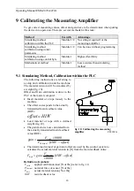
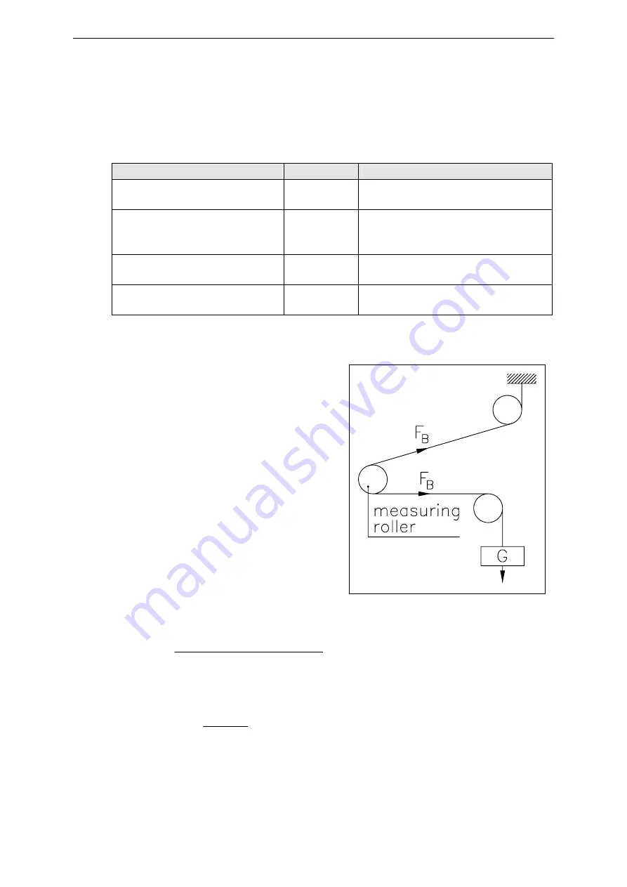
The following instructions are referring to
a setup and calibration inside the machine.
The material tension will be simulated by
a weight (fig. 10).
Offset and Gain calibration is done in the
PLC or the master computer.
•
Insert material or a rope loosely to the
machine.
•
The offset corresponds to the actually
transmitted main feedback value
(HIW):
HIW
offset
=
•
Load material or rope with a defined
weight (fig. 10)
•
The gain factor is now calculated from
the actually transmitted main feedback
value (HIW):
(
)
offset
HIW
F
F
gain
al
No
Calib
−
⋅
⋅
=
min
10000
•
The determined values for gain and offset are used by the control system to
calculate the actual material tension in [N] from the main feedback value:
(
)
offset
HIW
F
gain
F
al
No
Beff
−
⋅
⋅
=
10000
min
Definition of symbols:
F
Calib
applied calibration load [N or lbs] (refer to fig. 11)
F
Nominal
nominal force of sensor [N or lbs]
F
Beff
actual material tension [N or lbs]
HIW
main feedback value
fig. 10: Calibrating the measuring
amplifier
C431011e


