background image

操作指引

准备操作完成后,您可以按照本章指引开始使用本产品。

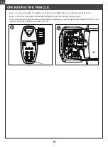
1、自动对码 (发射机和接收机在出厂前已对码成功。)

1. 发射器电源打开,对码模式,灯不停闪亮;
2. 接收板电源打开,前车灯不停闪亮,进入对码模式 ;
3. 当对码成功,发射机灯全亮,车上面的灯全部关闭 ;

如需更换其他的发射机或接收机,请按照如下步骤

进行对码:

注意 : 对码时请先操作发射机进入对码状态,再操作
接收机进入对码状态。

2、关机

1. 断开接收机电源。
2. 将开关拨到 [OFF] 位置,使发射机关闭。 

请按照以下步骤关机:

危险

关闭时,请务必先关闭接收机电源,再关闭发射机,

否则可能导致模型损坏、人员受伤。

27

使用前准备

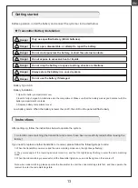
危险

请勿将电池置于高温环境或液体中。

危险

请勿打开、拆卸或自行维修电池。

危险

请勿挤压、刺穿或接触电池的金属端子。

危险

如果电池损坏,请立即停止使用。

危险

如果不按照说明方法操作,可能导致操作者或他人遭受较大伤害。

危险

请将电池存放在干燥阴凉的环境中。

危险

仅使用厂家指定的电池。

开始操作前,请按照本章的顺序和指引安装电池、连接设备。

发射机电池安装

1. 打开电池仓盖。
2. 将 4 颗电量充足的 AAA 电池装入电池仓内,确保电池上的金属端子与电池仓内的金属端子接触。
3. 盖好电池仓盖。

电池类型使用: AAA电池

请按照以下步骤安装发射机电池:

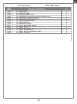
低电量报警:当电量低于4.2V时,面板上的LED慢闪报警提示

CN

Summary of Contents for FMS11221RTRGN

Page 1: ...Length 291mm Width 135mm Height 158mm Wheel base 187mm Ground clearance 16mm Approach angle 61 Departure angle 60 SPECIFICATION 1 12 jimny Manuel d utilisation Instruction Manual Bedienungsanleitung...

Page 2: ...THE VEHICLE CAR BODY ASSEMBLY CHASSIS ASSEMBLY COCKPIT ASSEMBLY FRONT AXLE ASSEMBLY MAIN GEAR BOX ASSEMBLY REAR AXLE ASSEMBLY SPRING SHOCK ASSEMBLY TRANSMISSION GEAR BOX ASSEMBLY STEERING GEAR Genera...

Page 3: ...other contaminants Always check the radio range of the vehicle prior to operation in order to prevent radio loss or interference Operate this product within your ability If the vehicle is dangerous to...

Page 4: ...e Statement This device complies with Part 15 of the FCC Rules Operation is subject to the following two conditions 1 this device may not cause harmful interference and 2 this device must accept any i...

Page 5: ...eople or roads 4 On any body of water when passenger boats are present Do not use this product when you are tired uncomfortable or under the influence of alcohol or drugs Doing so may cause serious in...

Page 6: ...ng Dual flash switch Fog lights Front rear fog lights can be activated remotely Brake lights Activated when parking Reverse lights Activated when reversing Realistic Body Details Lift the hood for a f...

Page 7: ...odel cars Transmitter intruction TransmitterOverview 1 2 3 4 5 6 7 13 12 14 16 15 17 18 8 9 11 10 1 Traversing handwheel 35 degrees on each side CH1 10 ST D R 2 Throttle button 25 degrees in front and...

Page 8: ...mensions 33mm 30mm 12mm Weight About 11g Certification CE FCC ID N4ZR4A10 08 Overview Specifications Binding The receiver automatically enters the binding state once it is powered on Press the BIND Ke...

Page 9: ...ng and when brake is applied the brake light is on with high brightness vice versa low light The headlights are in a low light state the tail lights and fog lights are always off Mode B In this mode w...

Page 10: ...he ESC We are not responsible for any damage caused by this Make sure the receiver is mounted away from motors or any device that emits excessive electrical noise Keep the antenna of the receiver at l...

Page 11: ...ger is moved back to the netural range and pushed to the reverse area for the second time it will reverse This mode is applicable to general models FWD REV This mode adopts one click reverse mode that...

Page 12: ...Reverse lights are on amid reverse opera tion Throttle linkage control Fog lamp Taillights Function Power on is off by default I II Control Mod Remarks OFF OFF OFF OFF OFF OFF OFF OFF OFF OFF III IV...

Page 13: ...battery compartment cover Battery Type AAA Battery Installation Low battery alarm When the battery is lower than 4 2V the LED on the panel will flash slowly Instructions After setting up follow the in...

Page 14: ...so may lead to damage or serious injury Product Model Channels Model Type RF RF Power 2 4GHz Protocol Distance Channel Resolution Battery Charging Interface Life time Low Voltage Warning Antenna Type...

Page 15: ...e stick position Top point of backward direction Top point of forward direction Neutral point 15 EN Connecting the battery VEHICLE SETUP Step 1 open the hood Step 2 place the battery in the battery bo...

Page 16: ...r the frequency matching mode Step 2 turn on the receiver switch the headlight will flash and enter the frequency matching mode Step 3 when the transmitter and receiver are successful in frequency up...

Page 17: ...17 CN 18 18 28 29 29 30 31 32 33 34 35 36 36 37 40 41...

Page 18: ...18 CN 14 FMS 14 14 3 MADE IN CHINA...

Page 19: ...19 1 2 3 4 2 4GHz CN...

Page 20: ...20 1 12 Jimny 1 12 JIMNY 180 CN...

Page 21: ...1 35 CH1 10 ST D R 2 25 12 5 CH2 11 TH D R 3 CH4 12 4 CH3 13 TH REV 5 14 LED G LED 6 4 AAA 15 BIND 7 ST REV 16 ST TRIM 8 LED R LED 17 TH TRIM 9 RX BATT 18 FS R4A1 ANT LED PWM 21 CN...

Page 22: ...ED 18 19 20 21 22 23 24 25 FS R4A1 FS MG41 4 7 2 4GHz ISM ANT Lipo 2S NiMH 5 7Cell BEC 6V 1A 10A 50A PWM 10 60 20 95 PPX4 33mm 30mm 12mm 11g CE FCC ID N4ZR4A10 22 G LED BIND 1 1 2 LED 1 10s 2 CN 12 11...

Page 23: ...1S 110 70 1 OFF M M 3Pin S A B C D 1 CH4 A B C D 2 3 C LED CN 23...

Page 24: ...90 194 1 2 a 3 0 c d 24 CN...

Page 25: ...ery Type Drag Brake 1 2 3 4 1 FWD REV BRK 1 FWD REV 2 Lipo 2 NiMH 3 4 0 3 4 50 3 4 75 3 4 100 1 Running Mode FWD REV BRK FWD REV 1 FWD REV BRK 1 FWD REV 2 Battery Type 2 2 3 Drag Brake 3 4 0 3 4 50 3...

Page 26: ...CH4 I II III IV V 6 1 0 5 0 5 3 1 0 5 0 5 3 1 0 5 0 5 26 CN...

Page 27: ...1 1 2 3 2 1 2 OFF 27 1 2 4 AAA 3 AAA 4 2V LED CN...

Page 28: ...CN 1 28 6V DC 1 5AAA 4 4 2V 1024 150m 10 C 60 C 20 95 CE FCC ID N4ZMG400 130g 118mm x 73mm x 145mm 4 AAA 2 4GHzISM ANT 20dBm FS MG41 4...

Page 29: ...1 2 29 1 2 3 CN...

Page 30: ...C1197 C1197 C1193 C1193 C1198 C1197 C1193 C1197 C1220 C1220 C1220 C1220 C1196 C1225 C1226 C1225 C1208 C1208 C1208 C1227 C1227 C1229 C1228 C1207 C1207 C1207 C1220 C1220 C1221 C1221 C1190 C1220 C1220 C1...

Page 31: ...SSEMBLY CN C1232 C1220 C1220 C1220 C1220 C1220 C1220 C1220 C1220 C1220 C1235 C1220 C1233 C1233 C1233 C1233 C1233 C1178 C1177 C1232 C1234 C1234 C1234 C1205 C1189 C1189 C1233 C1233 C1233 C1189 C1189 C12...

Page 32: ...MBLY CN C1209 C1210 C1218 C1216 C1216 C1216 C1218 C1218 C1218 C1219 C1219 C1220 C1220 C1220 C1220 C1201 C1217 C1215 C1220 C1220 C1220 C1220 C1201 C1220 C1220 C1220 C1220 C1220 C1199 C1199 C1199 C1199...

Page 33: ...187 C1182 C1187 C1194 C1182 C1183 C1186 C1194 C1195 C1182 C1183 C1186 C1194 C1195 C1177 C1178 C1181 C1194 C1195 C1182 C1185 C1194 C1182 C1185 C1194 C1182 C1186 C1194 C1182 C1186 C1194 C1182 C1183 C119...

Page 34: ...Y CN C1177 C1177 C1177 C1177 C1177 C1177 C1177 C1177 C1177 C1177 C1177 C1177 C1184 C1177 C1184 C1177 C1184 C1177 C1184 C1177 C1184 C1177 C1206 C1177 C1206 C1177 C1206 C1177 C1206 C1177 C1206 C1177 C12...

Page 35: ...35 EN REAR AXLE ASSEMBLY CN C1195 C1195 C1195 C1195 C1195 C1195 C1195 C1195 C1195 C1195 C1195 C1195 C1195 C1195 C1182 C1195 C1182 C1195 C1182 C1195 C1182 C1195 C1182 C1195 C1182 C1195 C1182 C1195...

Page 36: ...XPLODED VIEW 1 DE Chassis Explosionszeichnung 1 EN TRANSMISSION GEAR BOX ASSEMBLY CN EN SPRING SHOCK ASSEMBLY CN C1189 C1189 C1189 C1189 C1178 C1178 C1178 C1184 C1178 C1184 C1178 C1206 C1178 C1178 C11...

Page 37: ...37 EN STEERING GEAR CN C1211 C1188 C1211 C1211 C1211...

Page 38: ...IMNY STEERING HUB SET 1 12 JIMNY BRAKE DISC 1 12 JIMNY STEERING LINKAGE SET 1 12 4 0 BALL BULB 1 12 JIMNY SPRING SHOCK ASSEMBLY 1 12 JIMNY BUMPER 1 12 JIMNY REAR BUMPER 1 12 JIMNY WINDOW SET 1 12 JIMN...

Page 39: ...ROOF 1 12 JIMNY ANTENNA 1 12 JIMNY ROOF STAY BAR 1 12 JIMNY REARVIEW MIRROR AND INTERIOR PARTS 1 12 JIMNY HEAT DISSIPATION GRID 1 12 JIMNY RADIATOR GRILLE 1 12 JIMNY LOGO SET 1 12 JIMNY REAR DOOR 1 12...

Page 40: ...8 C1209 C1210 C1211 C1212 C1213 C1214 C1215 C1216 C1217 C1218 C1219 C1220 C1221 C1222 S S S S S S S S S S S S S S S S S S S S S S S S S S S S S S S S S S S S S S S S S S S S S S S S HT TX01 2 4G 1 12...

Page 41: ...NUMER PRODUCT DESCRIPTION S O S O CN C1223 C1224 C1225 C1226 C1227 C1228 C1229 C1230 C1231 C1232 C1233 C1234 C1235 S S S S S S S S S S S S S 1 12 1 12 1 12 1 12 1 12 1 12 1 12 1 12 1 12 1 12 1 12 1 1...

Page 42: ......

Page 43: ......

Page 44: ......

Reviews: