background image

Important ESC and model information

The ESC included with the model has a safe start. If the motor battery is connected to the ESC and the throttle stick is not in 

the low throttle or off position, the motor will not start until the throttle stick is moved to the low throttle or off position. Once the 

throttle stick is moved to the low throttle or off position, the motor will emit a series of beeps. Several beeps with the same tune 

means the ESC has detected the cells of the battery. The count of the beeps equals the cells of the battery. The motor is now 

armed and will start when the throttle is moved.

The motor and ESC come pre-connected and the motor rotation should be correct. If for any reason the motor is rotating in the 

wrong direction, simply reverse two of the three motor wires to change the direction of rotation.

The motor has an optional brake setting. The ESC comes with brake switched off and we recommend that the model be flown 

with the brake off. However, the brake could be accidentally switched on if the motor battery is connected to the ESC while the 

throttle stick is set at full throttle. To switch the brake off, move the throttle stick to full throttle and plug in the motor battery. The 

motor will beep one time. Move the throttle stick to low throttle or the off position. The motor is ready to run and the brake will 

be switched off.

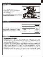
Battery Selection and Installation. We recommend the 11.1V 2200mAh 25C Li-Po battery. If using another battery, the battery 

must be at least a 11.1V 2200mAh 25C battery. Your battery should be approximately the same capacity, dimension and 

weight as the 11.1V 2200mAh 25C Li-Po battery to fit the fuselage without changing the center of gravity significantly.


1.

2.

3.

4.

9

1.Pull back on the latch, releasing the canopy.

2.Remove the canopy, revealing the battery compartment.

3.Apply hook and loop tape to the battery.

4.Install a fully charged battery into the battery compartment, with 

the battery cables facing aft.

Note: The center of gravity can be adjusted by moving the battery

forward or aft. Having the correct center of gravity is critical to 

achieving proper flight characteristics.

Battery  installation

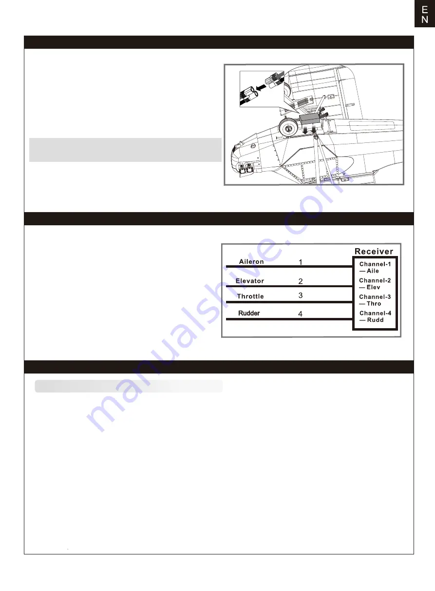
Receiver diagram

Preflight check

The cables from the servo connector board should be connected 

to your receiver in the order shown. Note that the LEDs can be 

powered by any spare channel on the receiver. Tuck the wire 

leads into the recessed cavity towards the rear of the battery 

hatch.

Summary of Contents for J-3 V3

Page 1: ...1400mm J 3 V3 FLOAT Optional float RIGID Strong durable EPO STABLE Smooth flying performance Manuel d utilisation Instruction Manual Bedienungsanleitung 操作手册 ...

Page 2: ...gs for this and any optional support equipment you use chargers rechargeable battery packs etc Keep all chemicals small parts and anything electrical out of the reach of children Moisture causes damage to electronics Avoid water exposure to all equipment not specifically designed and protected for this purpose Never lick or any place of any your model in your mouth as it could cause serious injury...

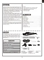
Page 3: ...ively for reconnaissance transporting supplies artillery spotting duties and medical evacuation of wounded soldiers Like its full sized counterpart the all new FMS 1400mm J 3 V3 has excellent short takeoff and landing STOL and slow speed handling characteristics FMS has dedicated significant amount of resources in making this aircraft as detailed as possible components such as the engine and landi...

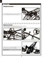
Page 4: ...uded screws as shown 3 Slide the tube into the fuselage then install both wings over the wing tube and into the wing slot of the fuselage Notice The connectors on both side should be attached precisely and firmly 1 Have the screws go through the supporting bar and then secure on the base 2 Lock up the fasteners of supporting bar on fuselage as shown E N PA2 6 15 KA2 0 8 PA2 6 15 ...

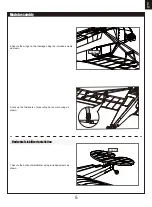
Page 5: ... Secure the wings on the fuselage using the included screws as shown 5 Lock up the fasteners of supporting bar on main wing as shown 1 Secure the horizontal stabilizer using included screws as shown 5 Model assembly E N HKM3 0 10 KA2 0 8 ...

Page 6: ... linkage rod to elevator control horn as shown Secure the linkage rod in place using the included screw as shown 2 Make sure the servos are in the neutral position Install the l inkage rod to rudder control horn as shown Note Please refer to the control horn and servo arm settings in page 11 E N Model assembly Linkage rod installation Vertical stabilizer installation KA2 0 12 KA2 0 8 ...

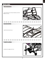
Page 7: ...truts to horizontal stabilizer and vertical stabilizer as shown 7 Model assembly Tail strut installation Antenna installation Propeller installation 1 Insert the antenna as shown 1 Assemble the propeller as shown a b c ...

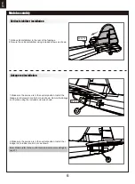
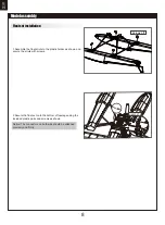
Page 8: ...cure the struts with screws 2 Secure the float set onto the bottom of fuselage using the included plastic parts and screws as shown Notice The connectors on both side should be attached precisely and firmly 8 Model assembly Float set installation Screws 3 4 HKM3 0 10 ...

Page 9: ...h the brake off move the throttle stick to full throttle and plug in the motor battery The motor will beep one time Move the throttle stick to low throttle or the off position The motor is ready to run and the brake will be switched off Battery Selection and Installation We recommend the 11 1V 2200mAh 25C Li Po battery If using another battery the battery must be at least a 11 1V 2200mAh 25C batte...

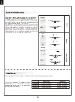
Page 10: ... in the OFF position Make sure both ailerons move up and down travel the same amount This model tracks well when the left and right ailerons travel the same amount in response to the control stick Move the controls on the transmitter to make sure the aircraft control surface moves correctly See diagrams right 10 Control throws The suggested control throw setting for the Piper J 3 Cub V3 are as fol...

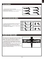
Page 11: ...dder Ailerons Check the C G Center of gravity When balancing your model adjust the battery as necessary so the model is level or slightly nose down This is the correct balance point for your model After the first flights the CG position can be adjusted for your personal preference 1 The recommended Center of Gravity CG location for your model is 55 65mm from the leading edge of the main wing as sh...

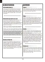
Page 12: ...ght set your timer to a conservative 4 minutes When your alarm sounds you should land right away 12 E N Before flying the model Flying course While applying power slowly steer to keep the model straight The model should accelerate quickly As the model gains flight speed you will want to climb at a steady and even rate It will climb out at a nice angle of attack AOA Flying Always choose a wide open...

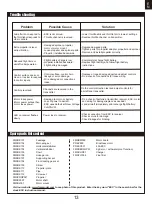
Page 13: ...ls reversed Channels are reversed in the transmitter Do the control direction test and adjust controls for aircraft and transmitter Motor loses power Motor power pulses then motor loses power Damage to motor or battery Loss of power to aircraft ESC uses default soft Low Voltage Cutoff LVC Do a check of batteries transmitter receiver ESC motor and wiring for damage replace as needed Land aircraft i...

Reviews: