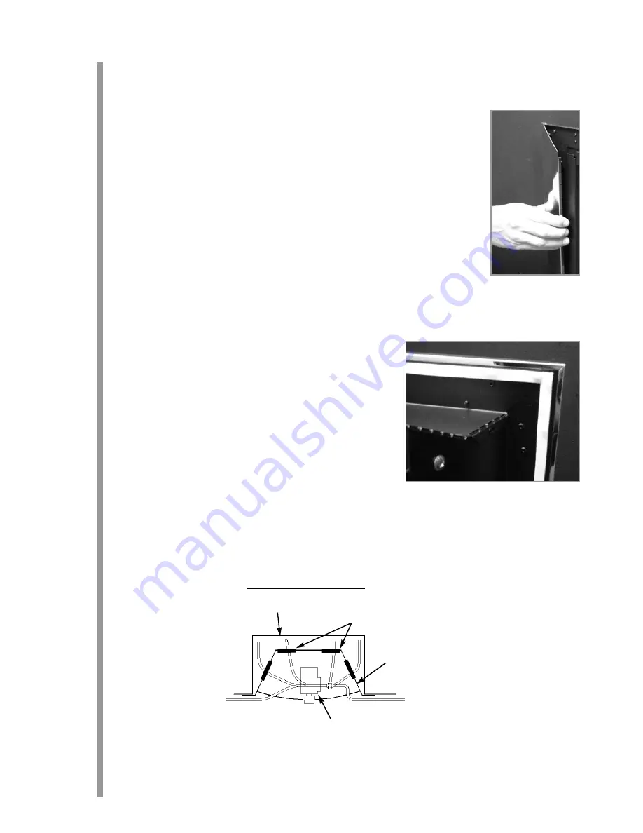
FITTING THE DECORATIVE FRAME
The appliance is supplied with a decorative frame. The frame attaches as a three piece clip-on assembly. If the
firebox is to be retained by the cable method, this is the most convenient stage at which to fit the three piece
clip on frame. Before fitting the frame remove any plastic protective coating. The side pieces of the clip on
assembly should be pushed into position first, followed by the top bar (shown), which should overlap the sides.
IMPORTANT N
NOTE: D
Due tto tthe ppossibility oof ssharp eedges,, ccare sshould bbe ttaken w
when hhandling tthe tthree ppiece
frame ccomponents. TThe uuse oof pprotective ggloves iis rrecommended. Place the firefront into position in front of
the fire and slide the ashpan door into place. Do not use any other firefront other than the one supplied with
this appliance. The firefront shown in these instructions may differ from the one supplied with the appliance.
PREPARING TTHE O
OPENING
Before installing the fire, check the flue using a smoke pellet. All of the smoke should travel up the flue and exit
correctly from the terminal. If problems are found, DO NOT fit the fire until corrective action is completed.
Protect the decorative hearth whilst pushing the firebox in and out of the opening. Part of the packaging will
make an ideal hearth saver pad.
Before running the gas supply into the opening, offer up the firebox to the fireplace to check the fit is good. Angle the firebox or adjust the
spigot outlet as described in the Fitting the Firebox section. Ensure that it slides in correctly, the sealing face sits flat and square to the wall or
infill panel, and that the base is firm on the floor of the opening as no leaks are permissible here. At this stage it is essential to ensure that the
spigot outlet of the fire is not restricted in any way. Remove the firebox and take any necessary measurements before making good and
preparing for final installation.
Apply the self adhesive sealing strips to the back of the fireframe to give a continuous
seal.
CABLE FIXING. For fixing of the fire by the cable method, see the relevant section.
The cable fixing locations should be marked on the back of the opening and the holes
drilled. Fit the fibre rawlplugs and eyebolts to these holes. Note: PPlastic rrawlplugs aare
NOT ssuitable ffor tthis aapplication.
SCREW FIXING. For fixing by screw, mark and drill the fireframe or base, and the rel-
evant points in the opening or on the wall. Rawlplugs will again be required. Pre-
punched holes are not provided for this purpose to allow you to choose the optimum
positions.
GAS SUPPLY. Following preparation for the fixing method, the concealed gas supply,
where required, can now be put into place. Refer to the gas supply section for sug-
gested pipe routes. The ends of the sleeving in which the gas pipe is run should be
sealed. The ends of the 8mm supply pipe should be temporarily sealed to prevent the ingress of debris during fixing.
GAS SUPPLY R
ROUTING
When the opening is ready for installation of the fire, the gas supply can be routed as shown in the diagram below. IMPORTANT - Wherever
a concealed connection is made a rubber grommet must be used to seal the firebox.
8.1
9.0
10.0
Grommets
Firebox
Fireplace opening
Gas valve
Suggested ggas ssupply rroutes
6
Summary of Contents for 18" High-Tech
Page 1: ......


