background image

INSTALLATION R

REQUIREMENTS

This appliance MUST NOT be installed into a room containing a bath or shower, or where steam may be
present. The fire has been designed to fit into a builders’ opening or fireplace conforming to BS 1251 (and meet-
ing certain dimensional requirements), or a suitable flue box complying with the constructional requirements of
BS 715. The flue box must be installed onto a suitable non-combustible insulating surface at least 12mm thick,
covering the entire base are of the box.

The flue must have an effective height of at least three meters, as measured from the hearth to the top of the flue.
Any flue damper plates or restrictors should be removed and no other restriction fitted to the flue. Where removal
is not practical, the restriction must be fixed in the fully open position.

A natural draught flue system is required, and if previously used for solid fuel or oil burning, the flue and chimney
must be swept prior to appliance installation. The flue must be checked before installation by using a smoke pel-
let or similar to ensure proper draw and that leakage is not evident at any joints. Repair and re-test as necessary
before the appliance is installed.

The flue must be connected to only one fireplace, and the flue must not vent more than one appliance (i.e. not
shared with a gas back boiler). There must be no opening in the flue apart from the one that the appliance is
installed into, and the one venting the gases into the air. A suitable terminal may be fitted, such as class GC1, as
regulations allow.

This appliance is suitable for use with a “lightweight” surround and back panel of 150ºc minimum rating.

SITE R

REQUIREMENTS

The fireplace opening should be inspected and repairs made where necessary. Any chair brick or fireback may
be left in place, providing that the dimensional requirements for debris collection and spigot clearance are met.

The opening WIDTH and HEIGHT dimensions should be between 400mm and 460mm wide, and 540mm to
570mm high.

Opening DEPTH should be 210mm or greater. Opening DEPTHS include any plaster or infill panels which form
part of the installation.

2

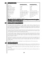
APPLIANCE D

DATA

Manual Control Version

Remote Control Version

Gas Group

G20 Natural Gas CAT I2H

G20 Natural Gas CAT I2H

Inlet Pressure

20 mbar

20 mbar

Max Energy Input (gross)

6.8 kW

6.8 kW

Min Energy Input (gross)

3.5 kW

3.5 kW

Pilot Energy Input (gross)

166 W

166 W

Setting Pressure (cold)

15.8 mbar (+/- 0.75mbar)

15.8 mbar (+/- 0.75mbar)

Main Injector Burner

Stereo size 81/Bray cat. 82/420 Stereo size 81/Bray cat. 82/420

Gas Inlet Connection

8mm Inlet Restrictor Elbow

8mm Inlet Restrictor Elbow

Gas Control Valve

Dungs BM 733/NGC 6802

Mertik Maxitrol GV34 Series

Ignition

Integral Piezo spark

Integral Piezo spark

Spark Gap

3.5 to 4.5mm

3.5 to 4.5mm

Weight

20 Kg

21 Kg

Please see Data Badge affixed to appliance for current data.

This aappliancce iis ffor uuse oonlyy w

with tthe ggas ttyype, aand aat tthe ppressure sstated oon tthe aappliancce

Data BBadge, aand iis ffor ddeccorative ppurposes.

2.0

3.0

4.0

Summary of Contents for Excelsior Expanse

Page 1: ... t to u user f for s safekeeping Revision A 05 04 Country s of destination GB IE Excelsior E X X P P A A N N S S E E Focal Point Fires plc Avon Trading Park Christchurch Dorset BH23 2BT Tel 01202 499330 Fax 01202 499326 www focalpointfires co uk e mail sales focalpointfires co uk ...

Page 2: ...d engineer be used for this purpose Read all these instructions before commencing installation This appliance must be installed in accordance with the rules in force and only used in a sufficiently ventilated space The appliance is designed for installation on to a non combustible hearth of at least 300mm depth This appliance is factory set for operation on the gas type and at the pressure stated ...

Page 3: ...applianc ce i is s f free f from a any a as sbes stos s m material R Refrac ctories s a and c coal b bed a are c cons struc cted f from c ceramic c f fibre Note R Remote c control m models s o only This appliance features a battery opearated remote control system and under normal usage will need new batteries approximately every twelve months Remote control Handset requirements 1 x PP3 type 9 volt...

Page 4: ...and the one venting the gases into the air A suitable terminal may be fitted such as class GC1 as regulations allow This appliance is suitable for use with a lightweight surround and back panel of 150ºc minimum rating SITE R REQUIREMENTS The fireplace opening should be inspected and repairs made where necessary Any chair brick or fireback may be left in place providing that the dimensional require...

Page 5: ... providing that it complies with the dimensions given below A non combustible shelf may be fitted to within 10mm of the top edge of the fireframe Combustible materials such as wood may be fitted to within 100mm 4in of either side of the frame of the appliance providing the forward projection does not exceed 100mm 4in Any combustible side walls must be at least 500mm to the side of the radiant heat...

Page 6: ...o a number of proprietory flue boxes provided that the minimum dimensions given in the diagram below are complied with The flue outlet of the fire must n not obscure the flue outlet from the flue box A smooth path into the flue must exist Cons struc ctional N Note The frame of the fire any back panel or other infill panel and the flue box must be sealed together so that there is no possibility of ...

Page 7: ...3 4 x AA remote control option only 1 Self tapping screw pack 3 Lengths of self adhesive sealing strip 1 Rubber grommet PREPARING T THE A APPLIANCE Note E Ens sure t that t the g gas s s supply i is s i is solated b before c com menc cing g i ins stallation o of t the a applianc ce The fireplace opening and environment must be in com pliance with the specifications laid down in the appropriate sec...

Page 8: ...ox is not restricted in any way Remove the firebox and take any necessary measurements before making good and preparing for final installation CABLE FIXING For fixing of the fire by the cable method see the relevant section The cable fixing locations should be marked on the back of the opening and the holes drilled Fit the fibre rawlplugs and eyebolts to these holes Note P Plas stic c r rawlplug g...

Page 9: ... positioned as close to the correct layout as possible Before finally fitting cables ensure the self adhesive sealing strips are in position on the back of the appliance frame The fireframe must be sealed evenly to the fireplace opening all around the periphery Thread the tensioning cables through the holes in the top of the fire box then the eyelets and finally through the lower holes in the back...

Page 10: ...ate is not already fitted attach with two screws ensuring the control knob is free to be depressed fully FUEL BED LAYOUT Coal E Effect O Option 1 Remove the combustion matrix from its protective packaging and position onto the burner tray as shown The front edge of the matrix should sit snugly behind the back edge of the burner rails Do not fit the matrix on top of the burner rails 2 Next remove t...

Page 11: ...stic effect Again remember not to push the coals down too far into the valleys between the coal supports as this can have a detrimental effect to the flame picture 5 Now take another six coals and place behind the second row of coals in order to complete the third row The coals may be orientated as desired to achieve a realistic effect Keep the spacing between the coals even and uniform 6 Finally ...

Page 12: ...x Care should also be taken not to push the pebbles right down between the supports as this can affect the flame picture when the appliance is running 3 Take five more ceramic pebbles and position as shown to form the second row of the fuel effect The pebbles may be rotated as desired to fit into the gaps between the supports in order to create a random realistic effect Again remember not to push ...

Page 13: ... bat teries Replace cover FITTING THE DECORATIVE FRAME AND FRONT The appliance is supplied with a decorative frame in a variety of finishes The frame is of three piece design and is held onto the firebox by magnets Firstly attach two magnets one at the top and one at the bottom to each side piece and then attach to the sides of the firebox frame Attach the remaining two magnets to the top piece an...

Page 14: ...THE F FIRE remote c control v versions The gas valve has two control knobs Turn the main burner control shown on left hand side of control valve knob fully anti clockwise Turn ignition knob shown on right hand side of con trol valve slightly left towards the ignition position until reaching the stop press down and hold for a few seconds until pilot gas is flowing Continue pressing down the knob wh...

Page 15: ...w but the meter pressure is acceptable then a problem in the supply pipework is to be suspected This will be dirt and debris kinked or inadequate size pipes restriction in a fitting or solder flashing across a joint NOTE you will not get an accurate reading of the inlet pressure with a pressure gauge on the end of the supply pipe this is the static pressure in the system You must use a T piece and...

Page 16: ...tructed on the safe use of the appliance and the need for regular servicing Frequency of service depends on usage but MUST be carried out at least one annually Scratched and other superficial damage to the matt black paintwork of the appliance can be covered with matching heatproof spray Use only the manufacturers recommended spray paint Paint only when the fire is OFF and cold Always mask off the...

Page 17: ... pro ceeding further Check the seal around the fireframe and replace if necessary Refitting of the firebox is described in the relevant section DISMANTLING T THE B BURNER T TRAY Remove the tray as previously described The pilot unit can be removed by undoing the tubing nut the thermo couple nut on the rear of the valve lint arrestor two securing screws and lifting away Remove the tubing nut from t...

Page 18: ... s f for a a t time a and t then c cuts s o off Excessive room draught or flue pull rectify Loose or faulty thermocouple rectify ODS system in operation Firebox grommet seal not fitted rectify Lint in pilot aeration hole clean thoroughly internally Pilot f flame s shrinks s w when f fire i is s o on h hig gh Poor gas flow to fire check pressure with fire on high If pressure is low remove any restr...

Page 19: ... further details on clearances to combustibles No combustible material or flooring should protrude onto the hearth DO NOT burn any foreign material on this fire the fuel effect must be of the correct type and laid out in accor dance with the relevant section of these instructions Failure to do so could create a hazard or lead to sooting Before the appliance is installed the chimney should be swept...

Page 20: ...ried out by your CORGI registered installer For Republic of Ireland ventilation may be required see IS 813 ICP3 IS 327 and any other rules in force OPERATING I INSTRUCTIONS manual v versions The pilot is visible through the left hand side of the front coal strip Push in and turn the control knob to the SPARK position and hold there for a few seconds Continue turning anti clockwise through the spar...

Page 21: ...an inbuilt safety feature to prevent the main burner being activated or turned up accidentally It is necessary to press but ton 1 and 2 see illustration simultaneously to turn the fire up To turn the fire down press button 3 only REPLACING T THE B BATTERIES remote c control v versions o only Handset Remove cover from rear of handset and insert 1 x PP3 9 volt battery Replace cover Appliance Ensure ...

Page 22: ...ace the front centrally against the fire after cleaning PAINTED AREAS These can be cleaned using a dry cloth COALS AND CERAMICS See the relevant section in the Installation Guide of these instructions Do not create dust from the coals Clean gently in the open air Replace components with original spares only as necessary LIST OF SPARES PA ART N NO ITEM CE F550012 Pack of 22 ceramic coals CE F550013...

Reviews: