CABLE FIXING
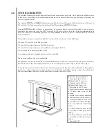
Drill four holes as shown in the diagram and fit the fibre rawl
plugs. If the fireplace does not allow for the exact layout shown,
the eyebolts should be fixed to give a similar configuration as
possible.
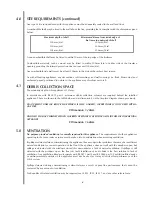
Thread both tensioning cables through the holes at the top of
the firebox, both eyelets, and back through the lower holes in
the firebox as shown in the photograph. Before finally fitting the
firebox, apply the self-adhesive sealing strips around the rear of
the firebox frame.
Push the appliance back into the fireplace, centralise and pull
the loose cables through the holes into the firebox.
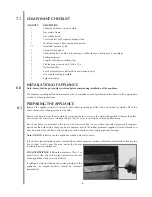
Thread the cable tensioners onto the cables as shown, with the nuts screwed
down close to the tensioner head.
Slide the screwed nipple onto the cable, pull
cable taut and tighten nipple.
Adjust tensioner using a suitable spanner to
pull the appliance back into position, to allow
an even seal around the fireplace opening.
Visually inspect the seal and reseat if
necessary.
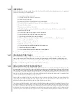
Surplus tension cable MUST NOT be cut off
as this will prevent proper installation after servicing. Coil up the surplus cable and tuck the coils out of the
way as suggested in the photograph.
FITTING THE BURNER TRAY
Important Note: Check that the thermocouple nut connection into the rear of the valve is secure.
Temporarily fit the burner tray and ensure a suitable gas route can be achieved. Place the burner tray into
the convector box making sure that the rear lugs locate properly on to the ledge in the firebox.
Fit the two securing screws through the tray legs to secure the assembly.
Connect the gas supply and tighten the gas connections.
Fit the data/control plate to the tray using the two screws
provided. Ensure that the control knob can be pushed fully
in and does not touch the plate.
Fit the deflector baffle to the two locations on the front face
of the firetray. Screws are provided for this purpose. The
baffle should be level with the lower edge of the tray. Place
the front casting in front of the fire temporarily to check the
angle of the baffle. The casting should fit well and the
control devices beneath should not be visible to the eye.
Realign the baffle slightly if necessary to achieve the correct
fit.
8
A. 250mm
B. 350mm
C. 60mm
Dimensions
+/-10mm
A
B
C
8.4
8.5


