Model 920 Ethernet Data Multiplexer Manual
Focal Technologies Corporation
Page 2-7
A Moog Inc. Company
920-0603-00 Rev K
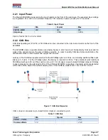
2.2.1 Input Power
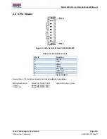
The Model 920 EDM is powered via the 8-pin header on the front of the enclosure. The expected input voltage
is a reg24V, and is non-isolated. Expect a 10% increase in power (inrush) for 0.1 seconds.
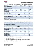
Table 6: Input Power
Input
Min
Typical
Max
24V IN - GND
20V
24V
28V
Amperage
0.16A
0.20A
Pin-8 is for 24V IN; Pin-7 is for GND.
2.2.2 CAN Bus
CAN Bus operating at 125, 250, or 500 KBaud can be connected to the terminal connector on the front of the
920 EDM.
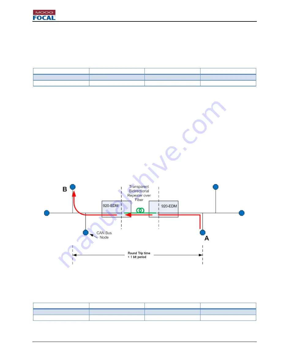
The 920-EDM uses a
repeater
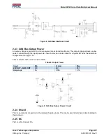
solution (see below figure) in which each unit transparently links near and far
sides of the optical link onto the same CANbus network. In order to satisfy CAN Bus bit-level arbitration, this
architecture relies on short optical and copper links to work.
Latency of the CAN Bus
repeater
solution for the 625 Mbps option is 400 ns, not including additional fiber optic
latency of ~5 ns/m. For the 2.5 Gbps option, the latency is reduced to 260 ns. These solutions work reliably at
500 KBaud with up to 20 m of fiber optics, and up to 10 m of copper on each linked CANbus network. CANbus
copper networks can be extended to 25m if the 2.5Gbps 920 EDM is specified. If network errors are detected
within these limits, adjust the default sampling time of the CANbus network from 75% to 87.5% of a bit.
Figure 7: CAN Bus Repeater
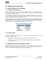
CAN L (low) is connected to pin-6 and CAN H (high) is connected to pin-5.
Table 7: CAN Bus
Input
Min
Typical
Max
CAN H
– CAN L
-6V
+6V
Common Mode
-7V
+12V


