Model 920 Ethernet Data Multiplexer Manual
Focal Technologies Corporation
Page 2-8
A Moog Inc. Company
920-0603-00 Rev K
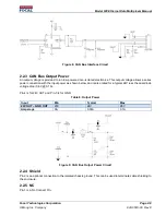
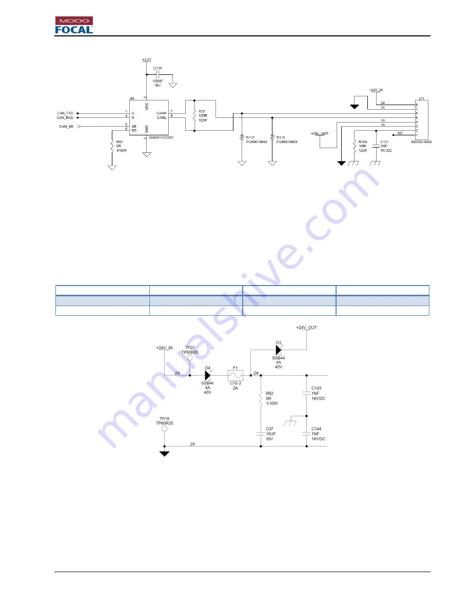
Figure 8: CAN Bus Interface Circuit
2.2.3 CAN Bus Output Power
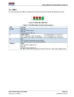
An output voltage is provided to run low powered non-isolated electronics. This output voltage allows a series
power connection with the input power as shown below, and is also rated for a typical 24V less the dual diode
voltage drop (0.6V @ 0.1A).
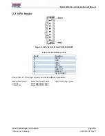
Pin-4 is for 24V OUT and Pin-3 is for GND.
Table 8: Output Power
Input
Min
Typical
Max
24V OUT
– GND OUT
20V
24V
28V
Amperage
0A
0.06A
0.1A
Figure 9: CAN Bus Output Power Circuit
2.2.4 Shield
Pin-2 is an optional connection to the isolated chassis ground. This can be used to terminate cable shielding to
the enclosure.
2.2.5 NC
Pin-1 is a No Connect Pin.


