background image


Model 920 Ethernet Data Multiplexer Manual 

Focal Technologies Corporation  

Page 5-4 

A Moog Inc. Company 

 920-0603-00  Rev K 

Diagnostics 

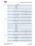
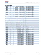
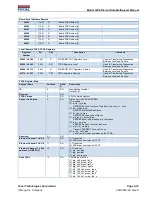
SFP REMOTE Rx Pwr High 

Warning 

Set when Received Power exceeds high warning level. 

SFP REMOTE Rx Pwr Low 

Warning 

Set when Received Power is below low warning level. 


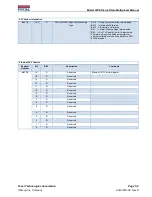
Reserved 


Reserved 


Reserved 


Reserved 


Reserved 


Reserved 


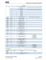
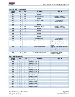
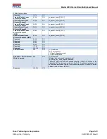
40009 

[15:0] 

SFP LOCAL Temperature 

Convert all analog values to little endian. 

40010 

[15:0] 

SFP LOCAL Voltage 


40011 

[15:0] 

SFP LOCAL Tx Bias 


40012 

[15:0] 

SFP LOCAL Tx Pwr 


40013 

[15:0] 

SFP LOCAL Rx Pwr 


40014 

[15:0] 

SFP REMOTE Temperature 


40015 

[15:0] 

SFP REMOTE Voltage 


40016 

[15:0] 

SFP REMOTE Tx Bias 


40017 

[15:0] 

SFP REMOTE Tx Pwr 


40018 

[15:0] 

SFP REMOTE Rx Pwr 


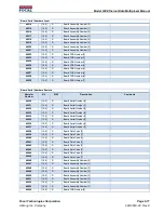
40019 

[15:0] 

Local Onboard Voltage ADC 

Reading:  1.2VDC 


40020 

[15:0] 

Local Onboard Voltage ADC 

3.3VDC 


40021 

[15:0] 

Local Onboard Voltage ADC 

24 VDC 


40022 

[15:0] 

Local Microcontroller Firmware 

Revision Number 


40023 

[15:0] 

Local Microcontroller Cause of 

Last Processor Reset 

0 = Power-up 

2 = Watchdog 

3 = Software Reset 

4 = User (NRST pin) 

5 = Brownout 

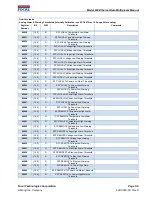
40024 

[15:0] 

Remote Onboard Voltage ADC 

Reading:  1.2VDC 


40025 

[15:0] 

Remote Onboard Voltage ADC 

3.3VDC 


40026 

[15:0] 

Remote Onboard Voltage ADC 

24 VDC 


40027 

[15:0] 

Remote Microcontroller Firmware 

Revision Number 


40028 

[15:0] 

Remote Microcontroller Cause of 

Last Processor Reset 

0 = Power-up 

2 = Watchdog 

3 = Software Reset 

4 = User (NRST pin) 

5 = Brownout 


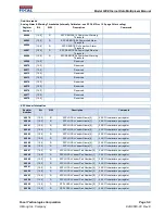
One-time reads 

Analog Alarm & Warning Thresholds (Internally Calibrated - see SFF-8472 rev 10.2 page 24 for scaling) 

Register 

Number 

Bit 

R/W 

Description 

Comments 

40029 

[15:0] 

SFP LOCAL Temperature High Alarm 

Threshold 


Summary of Contents for Moog 920

Page 1: ...LY GRANTED BY CONTRACT OR BY OPERATION OF LAW NO PORTION OF THIS DATA DRAWING DOCUMENT SHALL BE REPRODUCED OR DISCLOSED OR COPIED OR FURNISHED IN WHOLE OR IN PART TO OTHERS OR USED BY OTHERS FOR ANY P...

Page 2: ...26 Rev F Updated CANBus specifications for 2 5 GBaud Mode EM 2014 Apr 8 Rev G Updated to include new Single Mode part numbers EM 2014 Nov 25 Rev H Updated cover page header and footer to include new F...

Page 3: ...7 2 2 2 CAN Bus 2 7 2 2 3 CAN Bus Output Power 2 8 2 2 4 Shield 2 8 2 2 5 NC 2 8 2 3 LEDs 2 9 2 4 Optics 2 10 2 4 1 Optical Safety 2 12 3 0 Diagnostics Functionality 3 1 3 1 Network Settings and Acces...

Page 4: ...50 2 11 Table 12 Optical Interface Parameters for 920 8000 02 and 920 8001 02 2 5GBaud SMF 1310 1550 2 11 Table 13 Factory Default Network Parameters 3 1 Table 14 Electrical Specification 6 3 Table 15...

Page 5: ...Gbps Gigabits Per Second I O Input output kbps Kilobits Per Second LC PC Lucent Connector Physical Contact LED Light Emitting Diode Mbps Megabits Per Second MDI MDIX Automatic medium dependent interfa...

Page 6: ...his document provides Model 920 EDM users with detailed information relevant to the design configuration installation and operation of the Model 920 EDM This manual and the appropriate reference docum...

Page 7: ...ltiplexer CWDM to take advantage of the high bandwidth of optical fiber Figure 2 represents a block diagram of the flow of data through the Model 920 EDM Figure 2 illustrates an example of a system co...

Page 8: ...and auto crossover capabilities are provided CAT5 or better cabling is recommended for all installations with a maximum cable length of 100m 2 1 2 EtherCAT Ports 1 and 2 100 Base TX All packets to fro...

Page 9: ...10 100 BASE T X RJ45 LED Indication Position LED Function Left Top Green Link Blinking Green Activity Right Bottom Yellow 100Mbps Off 10 Mbps 2 1 3 EtherCAT Link Latency The Model 920 EDM is designed...

Page 10: ...the Model 920 system NOTE A 1000 BASE T link is possible for port 3 if forced Throughput is limited to 100 Mbps for the 625 MBaud version of the Model 920 EDM If packets are being dropped ensure that...

Page 11: ...ng end of the system will be forced off to communicate to host electronics that the link has been lost Similarly when the Ethernet achieves link if the opposing end has been forced off in this channel...

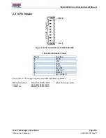
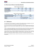
Page 12: ...6 8 Pin Header Molex P N 502352 0800 Table 5 8 Pin Header Pinout Pin Function 8 24V IN 7 GND 6 CAN L 5 CAN H 4 24V OUT 3 GND OUT 2 SHIELD 1 NO CONNECT See section 6 1 for mating connector and cable i...

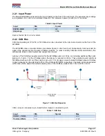
Page 13: ...ar and far sides of the optical link onto the same CANbus network In order to satisfy CAN Bus bit level arbitration this architecture relies on short optical and copper links to work Latency of the CA...

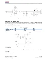
Page 14: ...eries power connection with the input power as shown below and is also rated for a typical 24V less the dual diode voltage drop 0 6V 0 1A Pin 4 is for 24V OUT and Pin 3 is for GND Table 8 Output Power...

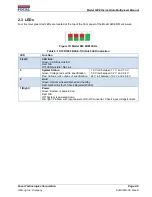
Page 15: ...Left CAN Bus Green CAN Bus Link Act Red N A Off CANbus Idle No Link 3 System Status Green Voltage rails within specification Red Voltage rails outside of specification 1 2 V rail between 1 1 V and 1 3...

Page 16: ...components 2 km Data Rate 625 MBaud Transmit Transmitter Centre Wavelength P N 920 8000 00 1260 1310 1360 nm Transmitter Centre Wavelength P N 920 8001 00 1500 1550 1580 nm Average Output Power 13 8 d...

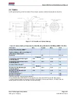
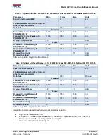
Page 17: ...n may limit optical distance Table 12 Optical Interface Parameters for 920 8000 02 and 920 8001 02 2 5GBaud SMF 1310 1550 Parameter Min Typical Max Unit 9um Core Diameter SMF Typical distance with no...

Page 18: ...DM system are Class I laser devices per IEC 60825 unless otherwise specified in installation or configuration drawing No special control measures or warning labels are required although any needless e...

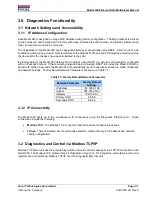
Page 19: ...support DHCP to provide the Model 920 with a dynamic IP within 30 seconds the Model 920 will automatically revert to use locally stored i e static IP address and network settings Factory Default Netwo...

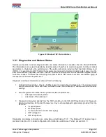
Page 20: ...current over time can indicate aging of the laser and assist with life predictions Diagnostic and status information is retrieved from the following 1 Onboard microcontroller A bank of ADCs is used to...

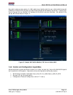
Page 21: ...for local PLCs and other controllers A screenshot of the sample GUI is shown below in Figure 13 Figure 13 Sample NET GUI for Modbus TCP Access to Model 920 3 2 2 Control and Configuration Capabilities...

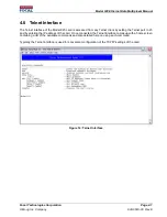
Page 22: ...cessed from any Telnet client by setting the Telnet port to 23 and by entering the IP address of the card Once connected the Telnet interface comes up with a home screen containing a list of the avail...

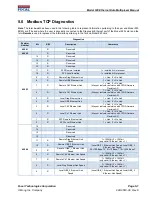
Page 23: ...Link 1 Link 0 No Link May not indicate real status with FPGA firmware Revision A2 5 R Local Diag Ethernet Link 1 Link 0 No Link 4 R Local GBE Ethernet Link 1 Link 0 No Link 3 R Local Ch2 Ethernet Link...

Page 24: ...power exceeds high alarm level 8 R SFP LOCAL Tx Pwr Low Alarm Set when TX output power is below low alarm level 7 R SFP LOCAL Rx Pwr High Alarm Set when Received Power exceeds high alarm level 6 R SFP...

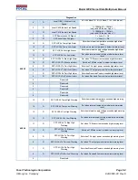
Page 25: ...wr Low Alarm Set when TX output power is below low alarm level 7 R SFP REMOTE Rx Pwr High Alarm Set when Received Power exceeds high alarm level 6 R SFP REMOTE Rx Pwr Low Alarm Set when Received Power...

Page 26: ...R SFP REMOTE Rx Pwr 40019 15 0 R Local Onboard Voltage ADC Reading 1 2VDC 40020 15 0 R Local Onboard Voltage ADC 3 3VDC 40021 15 0 R Local Onboard Voltage ADC 24 VDC 40022 15 0 R Local Microcontroller...

Page 27: ...arm Threshold 40043 15 0 R SFP LOCAL Tx Power High Warning Threshold 40044 15 0 R SFP LOCAL Tx Power Low Warning Threshold 40045 15 0 R SFP LOCAL Rx Power High Alarm Threshold 40046 15 0 R SFP LOCAL R...
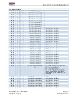
Page 28: ...0 R SFP LOCAL Vendor Name 2 2 ASCII characters per register 40082 15 0 R SFP LOCAL Vendor Name 3 2 ASCII characters per register 40083 15 0 R SFP LOCAL Vendor Name 4 2 ASCII characters per register 4...

Page 29: ...7 15 0 R SFP LOCAL Focal PN 7 2 ASCII characters per register 40118 15 0 R SFP LOCAL Focal SN 0 2 ASCII characters per register 40119 15 0 R SFP LOCAL Focal SN 1 2 ASCII characters per register 40120...

Page 30: ...Serial Number 5 40152 15 0 R SFP REMOTE Serial Number 6 40153 15 0 R SFP REMOTE Serial Number 7 40154 15 0 R SFP REMOTE Date Code 0 2 ASCII characters per register 40155 15 0 R SFP REMOTE Date Code 1...

Page 31: ...t 7 1 Alarm Warning Flags Implemented Bit 6 1 Soft Tx Disable Control Implemented There are no reserved Modbus registers for external calibrated values More details in SFF 8472 document Ethernet PHY C...

Page 32: ...f I2C errors detected after power up The counter is reset after a power cycle or after the max count is reached 40191 15 0 R I2C Error Counter Remote 16 bit value that indicates the number of I2C erro...

Page 33: ...umbers Remote Register Number Bit R W Description Comments 40230 15 0 R Board Serial Number 0 40231 15 0 R Board Serial Number 1 40232 15 0 R Board Serial Number 2 40233 15 0 R Board Serial Number 3 4...

Page 34: ...dress RW R O Description ID 0 RO Identification Number Default 01 Reserved 1 RO FPGA Version 2 RO FPGA Version Number Optical Link Status 3 RO Status from the FPGA SERDES 7 reserved 6 rx_cdr_lol_diag...

Page 35: ...unt 3 31 0 Receive Packet Count Ethernet Channel 3 GBE 47 44 RO rx_packet_count 3 31 0 Reserved 51 48 RO Reserved 55 52 RO Reserved 59 56 RO Reserved 63 60 RO Reserved 127 64 RO Reserved 243 128 RW St...

Page 36: ...dent on the fiber type and environment Avoid even temporary bends with a radius less than 15 mm which may affect the long term reliability of the fiber It is important that the 8 lead power and CANbus...

Page 37: ...errules or excessive fiber bends It is good practice to carefully clean all fiber connections prior to mating them for testing If the basic optical link is present there should be good Ethernet data c...

Page 38: ...various components using the methods described below Dust or dirt on the cards can be blown off using compressed air If severe contamination of the cards should occur they can be removed and cleaned u...

Page 39: ...ved away from their intended routes Ensure any disconnected optical connectors are cleaned immediately prior to reconnection Do not exceed the recommended minimum fiber bend radius even momentarily Mi...

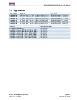
Page 40: ...001 01 2 5Gb s MMF 1550nm 10DBM DIAGNOSTICS 920 EDM HS MMJ15 10 DIN F 920 8000 02 2 5Gb s SMF 1310nm 20DBM DIAGNOSTICS 920 EDM HS SMJ13 20 DIN F 920 8001 02 2 5Gb s SMF 1550nm 20DBM DIAGNOSTICS 920 ED...

Reviews: