Model 920 Ethernet Data Multiplexer Manual
Focal Technologies Corporation
Page 6-1
A Moog Inc. Company
920-0603-00 Rev K
6.0
Installation and Operation
6.1 Installation
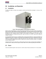
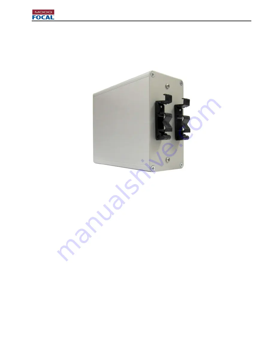
The Model 920 EDM is intended to be installed on a DIN rail with the DIN mount adaptor on the rear on the
enclosure.
Figure 15: Model 920 EDM Rear with DIN Rail Mount Adaptors
When mounting, disassembling, or reassembling the Model 920 EDM, ensure that no fibers are subjected to
bends in excess of those held by the natural routing of the fibers. The minimum bend radius of the fibers should
generally be no less than 25 mm, though single partial bends may be less than this
– as low as 15 mm – without
damaging the fiber. Allowable long term values for bend radius are dependent on the fiber type and
environment. Avoid even temporary bends with a radius less than 15 mm, which may affect the long-term
reliability of the fiber.
It is important that the 8-lead power and CANbus cable is properly assembled with no exposed conductors and
appropriate strain relief. The power and data leads must be twisted in pairs, 24V IN with GND, 24V OUT with
GND OUT, and CANL with CANH. The cable assembly must not put undue stress or torque on the connector
or the modem itself. Suggested cable harness receptacles and crimp tools are listed in Section 2.2. All Materials
must be corrosion resistant.
All Ethernet ports require 8 lead CAT5 or CAT6 cabling. Inspect all plugs for damage before installation. No
excessive strain or torque should be applied to these cables, as this could damage the jack and/or modem.
6.2 Power
Power is provided through the 8-pin connector on the front panel. Please see Section 2.2.1 for more details.

