IIN
NSSTTA
ALLLLIIN
NG
G TTH
HEE A
APPPPLLIIA
AN
NC
CEE
To ensure the appliance is positively located into position, it is necessary to secure it in
place using one of the following methods, either with the cable fixing kit, or the dou-
ble-sided neoprene strips included in the instruction pack.
Fixxing bby nneoprene sstrips
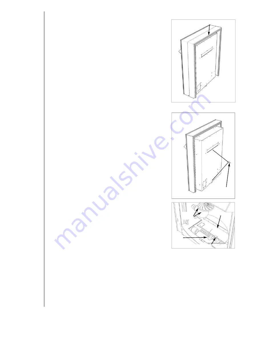
In normal installation circumstances, this method of fixing is satisfactory for use with
marble, stone, laminate, or any smooth faced mounting surface. Peel off the adhesive
backing from one side of each strip and apply to the periphery of the REAR of the
appliance frame, as shown in the Fig.1. Ensure that the strips are not applied any closer
than 5mm (1/4”) from the edge of the frame, attaching the strips closer may present
problems when fitting the decorative trim. Tear off any excess lengths of strip to form a
neat border around the frame.
Before finally fitting the appliance into its location, remove the remaining strips of
adhesive backing, ensure that the mains cable and plug are properly routed, locate the
fire into the opening and press firmly around the edge of the frame to allow the strips
to adhere to the back panel of the surround.
Fixxing bby ccable ffixxing kkit
This method of securing is normally necessary when the mounting surface is of a
rough texture, i.e. stone or brick.
Firstly mark and drill a suitably sized hole in the centre of the proposed appliance loca-
tion, 250mm up from the hearth surface, or floor if no hearth is to be used. Insert the
rawlplug into the hole, then screw in the eyebolt.
Remove the fuel bed by removing the frame, pebbles and removing the screw attach-
ing the fuelbed to the appliance ‘shelf.’Insert the cable through the central hole in the
back of the appliance (Fig.2), through the eyebolt and through the hole in the lower
rear of the appliance. Remove the light bulb from its mounting by pushing it in and
twisting (if necessary the spinner assembly can also be removed - 2 screws through
spinner bar). Locate the appliance into its opening and pull the cable taught. Slide on
the screwed nipple and keeping the cable reasonably taught, tighten the nipple to
secure (Fig.3). Replace the light bulb (and spinner). The remainder of the cable may
be coiled up and neatly coiled in the base. Fit the fuel bed and frame.
NOTE: When uusing tthis ccable ffixing m
method,, tthe aadditional ddepth oof tthe eeyebolt m
must
be ttaken iinto aaccount. TTherefore,, uusing tthis m
method w
will iincrease tthe m
minimum m
mount-
ing ddepth oof tthe aappliance tto 880mm.
FITTING THE DECORATIVE FRAME AND FRONT
The appliance may be supplied with a decorative frame, with an integral firefront.
IMPORTANT :: D
Due tto tthe ppossibility oof ssharp eedges,, ccare sshould bbe ttaken w
when hhan-
dling tthe fframe ccomponents. TThe uuse oof pprotective ggloves iis rrecommended.
Remove the protective film from the frame, bars and ashpan and place the frame on a
flat surface. Slide each bar on to the tags on one leg of the frame. Lift the other leg
until the bars meet with the tags on this leg. Do nnot bbend tthe bbars. Slide the bars
carefully on to the tags. Screw the handle on to the ashpan.
Attach the frame to the appliance using the four magnetic pieces provided, on to each
corner of the appliance frame.
Place the ashpan centrally below the bars.
ASSEMBLING TTHE FFUEL BBED
1.
Disconnect the appliance from the mains.
2.
Remove the loose pebbles from their packaging. Position the pebbles onto
the white fuel bed ‘shelf’ and down behind the frame bars, so as to create a
realistic effect.
3.
Unpack the decorative frame, follow the assembly instructions enclosed
with them, and attach to the appliance frame with the magnets provided .
Lulworth Models: The pebbles should not be placed over the shelves ‘holes’, which are below the curved panel. These should be left, at
least particially un-obscured, so that the effect can be seen on the rear panel.
OPERATING THE APPLIANCE
Check that the fan outlet is not covered or obstructed in any way and ensure the power to the fire is switched on.
The appliance is controlled using four switches, mounted under the lift up hood. The left switch (OI) controls the main power to the fire and
switches on the fuel effect, which can be used independently of heat for visual effect only. The second switch (*) operates the fan blower
without heat, which can be used in the summer for cool air circulation. The switch marked with a single bar (I) operates the fan heater on
the LOW setting (1kW). The switch marked with two bars (II) operates the fan heater on the HIGH setting (2kW).
6.0
6.1
7.0
2
Cable
Fig.3
Rear
Panel
Screwed Nipple
Neoprene Strip
Fig. 1
Fig. 2
Cable
Eyebolt
screwed into
rear of opening
5.0
Bulb &
Spinner


