9
Handler I, II & III Operator’s Manual - October 2008
Assembly & Installation
About Your Handler
Model Type
You have purchased a Handler I, Handler II or Handler III. All
components required to install the unit are included in the pack-
age except for the fittings used to join the Handler tank to the
existing sprayer lines. Purchase these from your dealer as the
size may vary between make and model of sprayer.
Valve System
All systems have been equipped with a venturi or plumbing
valve system. Identify precisely the model type and valve system
you have purchased before you begin assembly and installation
Assembly and installation procedures are specific to each model
type and valve system. Because installation varies, the assembly
instructions and illustrations will separately detail the installation
of each model type.
Handler I Assembly
Overview
Assembly and instructions of your Handler 1-i15T threaded ver-
sion follows five basic steps:
Install agitation and rinse valve assemblies onto side of
tanks.
Install venturi valve assembly with venturi onto bottom of
tank.
Install venturi bracket onto Handler frame.
Install bypass valve assembly.
Install hoses and clamps.
Assembly and instructions of your Handler 1-i15M Manifold
version follows five basic steps:
Assemble and install agitation and rinse valve assemblies
onto side of tanks.
Assemble and install venturi valve assembly with venturi
onto bottom of tank.
Assemble and install remaining manifold fittings.
Install venturi bracket onto Handler frame and bolt down
manifold fittings to bracket.
Install hoses and clamps.
1.
2.
3.
4.
5.
1.
2.
3.
4.
5.
Threaded System
Step 1
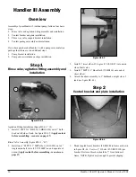
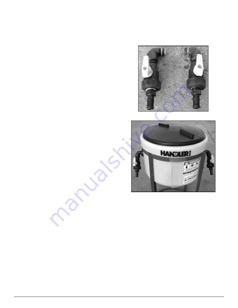
Agitation and rinse valve installation
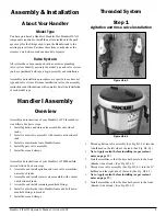
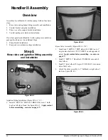
Figure H1-4.1
Figure H1-4.2
Thread agitation valve assembly (See Fig. H1-4.1) into the
¾ bulkhead on the left side of the tank. (See Fig. H1-4.2)
Note: Apply sealant before installing (as per sealant
notes on page 37.)
Install assemblies so that the hose barb points to the front.
(Bracket side of tank.) (See Fig. H1-4.2)
Thread rinse valve assembly (See Fig. H1-4.1) into the ¾”
bulkhead on the right side of the tank. (See Fig. H1-4.2)
Note: Apply sealant before installing (as per sealant
notes on page 37.)
Install assemblies so that the hose barb points to the front.
(Bracket side of tank.) (See Fig. H1-4.2)
1.
•
2.
3.
•
4.
Summary of Contents for Handler I
Page 2: ......
Page 48: ...48 Handler I II III Operator s Manual October 2008...

