background image

44

Handler I, II & III Operator’s Manual - October 2008

Plumbing Package 

Assembly

(Handler 3)

Overview

Although not very common, some customers prefer to purchase 
and use the Handler as an induction system rather than an educ-
tion system.  In the induction system the venturi is removed and 
the pump is used to both pressurize the system when adding 
fresh water through agitation and when rinsing containers with 
fresh water, and to remove mix liquids and concentrated chemi-
cal solutions from the tank.  This appendix to the Handler I, II 
& III manual gives assembly and operational instructions for 
the Handler III plumbing package systems offered by Focus 
Industries.

Assembly & Installation

Handler III 2” Manifold Plumbing

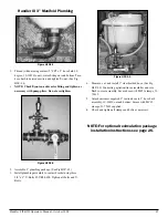
Figure H3P-4.1

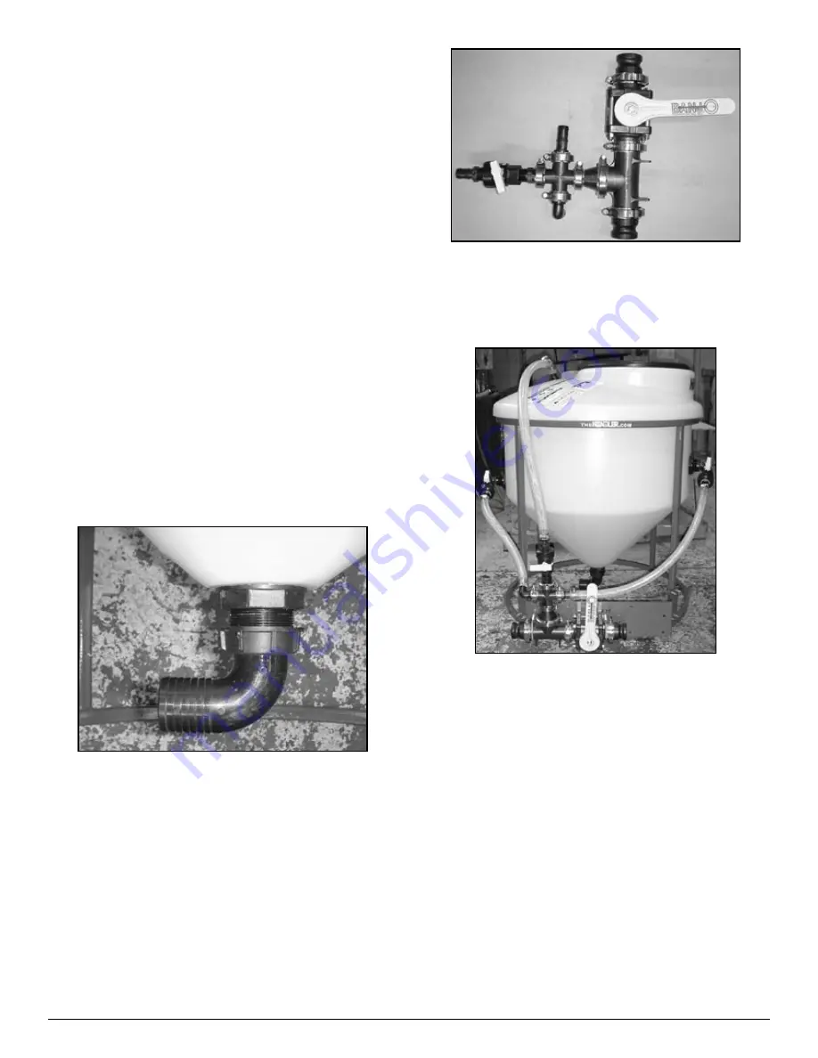
Thread (without using sealant) 2” FPT x 2” hose barb 90 
degree, 10-10930 to anti-vortex fitting on tank bottom. Turn 
hose barb to desired position and tighten fly-nut. (See Fig 
H3P-4.1)

NOTE: Check flynut on anti-vortex fitting and tighten as 
necessary with pump pliers. Do not overtighten.

1.

Figure H3P-4.2

Assemble 2” plumbing package. (See Fig H3P-4.2)
Install plumbing assembly to venturi bracket using bolts and 
U-bolts provided.  Tighten.

Figure H3P-4.3

Measure, cut and install 1” hose (See Fig H3P-4.3) con-
necting agitation/rinse assemblies and RotaFlush to cross.  
Secure hose with clamps.
Attach customer supplied 2” suction hose to 2” hose barb 
assembly on tank bottom.  Secure with clamps provided.
Check and tighten all clamps and bolts as necessary.

NOTE: For optional recirculation package 

installation instructions see page 26.

2.
3.

4.

5.

6.

Summary of Contents for Handler I

Page 1: ...allation 9 Handler II Installation 14 Handler III Installation 20 Operation 28 Troubleshooting 36 Handler I Manifold Venturi Package Breakdown 38 Handler I Threaded Venturi Package Breakdown 39 2 Hand...

Page 2: ......

Page 3: ...by others in such manner as in our judgment affects the product materially and adversely shall void this warranty Warranty does not apply to any machine or part which has been repaired or altered in a...

Page 4: ...ate Code City State Code Phone Number Phone Number Delivery Date Check One Commercial Use Farm Use Serial Number of Unit Dealer Inspection Report Safety Frame Fasteners Tight All Decals Installed Chem...

Page 5: ...e or allow anyone else to operate this equipment until such information has been reviewed Annually review this information before season start up Make these periodic reviews of Safety and Operation a...

Page 6: ...tions left right front and rear as mentioned throughout this manual are seen from the operator s position facing the front of the Handler tank With the proper orientation the Handler name will be clea...

Page 7: ...erating instructions in the manual and to follow them All accidents can be avoided A person who has not read and understood all operating and safety instructions is not quali ed to operate the machine...

Page 8: ...area is clean and dry Decide on the exact position before you remove the backing paper Remove the smallest portion of the split backing paper Align the decal over speci ed area and carefully press the...

Page 9: ...valve assembly with venturi onto bottom of tank Install venturi bracket onto Handler frame Install bypass valve assembly Install hoses and clamps Assembly and instructions of your Handler 1 i15M Mani...

Page 10: ...sing 5 16 x bolts Do not tighten completely yet See Fig H1 4 4 1 2 3 Figure H1 4 5 Attach bypass valve assembly to venturi assembly using stainless steel ange clamp 25 FC200 and gasket 25 150G making...

Page 11: ...i15T is now completely assembled Instructions for the manifold package will follow You may now continue to the operation section of the manual starting on page 28 2 3 1 2 Manifold System Step 1 Agita...

Page 12: ...me See Fig H1 4 10 Continue attaching manifold ttings using the appropriate clamps and gaskets as shown See Fig H1 4 10 Note Make sure venturi nozzle is in place before install ing venturi hose Make s...

Page 13: ...bly Again fasten hose with MC12 clamps See Fig H1 4 13 Figure H1 4 14 Measure then cut and attach the appropriate length of 1 PVC suction hose 54 79050 to connect the venturi to the manifold tting ass...

Page 14: ...ve and agitation tting assembly and installation FIgure H2 4 1 Agitation Fitting Installation Figure H2 4 1 A Install 1 MPT X 1 HB 90 25 HB100 90 on to 1 bulk head on left side of tank See gure H2 4 2...

Page 15: ...ounting plate 86 HVMP on to angled frame brackets as shown in gure H2 4 5 Use three 5 16 X 1 bolts 67 CSH5C516 1p two on the right side and one on the lower left side Do not tighten completely yet Hin...

Page 16: ...as sembly easier Open FC100 clamps completely to make assembly easier 1 2 Part Number 25 M220CPG90 has long and short side At tach short side to venturi and long side to 3 way ball valve 25 MV220BL a...

Page 17: ...bly to plate Do not tighten completely yet Figure H2 4 10 Assemble remaining 2 ttings as shown in gure H2 4 10 2 3 4 Figure H2 4 11 Mount second assembly to rst as shown in gure H2 4 11 use 25 FC220 c...

Page 18: ...gure H2 4 14 Hint Install hose at bottom end and ensure proper length Heat other end and install hose barb Attach hose barb to assembly Measure cut and install 1 clear braided hose 54 79210 for agitat...

Page 19: ...tion Mount pump to pump bracket using four 5 16 X 1 L bolts four 5 16 locking nuts and eight at washers Figure H2 4 19 Install 2 Tee 10 11100 to bottom of tank use pipe seal ant see gure H2 4 19 1 2 1...

Page 20: ...B 90 25 HB100 90 on to 1 bulk head on left side of tank See gure H3 4 2 Apply sealant before assembling see notes on page 37 Rinse Valve Assembly gure H3 4 1 B Install one 1 MPT X 1 MPT elbow 10 10980...

Page 21: ...86 HISP to frame as shown in gure H3 4 6 Use two 1 U bolts 67 UB025 100 four washers and four locking nuts Do not tighten com pletely yet Go to next step Three way valve support bracket installa tion...

Page 22: ...de At tach short side to venturi and long side to 3 way ball valve 25 MV220BL as shown in gure H3 4 7 Start assembly at discharge end and work towards other end 2 3 intake Venturi comes with nozzle in...

Page 23: ...sket Do not tighten completely yet Install 2 U bolts 67 UB038 250 to hold second as sembly to intake support plate See gure H3 4 11 Do not tighten completely yet 4 5 6 Figure H3 4 13 Assemble 1 ttings...

Page 24: ...tation and jug rinse lines Secure with clamps 53 75612 Figure H3 4 16 Install 2 FPT X 1 hose barb 90 degree tting on to bot tom of tank see gure H3 4 16 13 14 15 Figure H3 4 17 Measure cut and install...

Page 25: ...to hold assembly to plate Do not tighten completely yet Figure H3 4 20 2 3 Figure H3 4 21 Assemble remaining 3 ttings as shown in gure H3 4 20 Mount second assembly to rst as shown in gure H3 4 21 use...

Page 26: ...e cut and install 1 clear braided hose 54 79210 for agitation jug rinse and Rota ush lines Secure with clamps 53 75612 Install 2 FPT X 1 Hosebarb 90 degree tting on to bot tom of tank see gure H3 4 16...

Page 27: ...drilling extra holes in plate 2 3 4 Three inch pump and recirculation package installation Figure H3 4 29 Mount pump to Z rails using four 5 16 X 1 bolts Mount pump to pump bracket using four 5 16 X 3...

Page 28: ...Review safety instructions annually How the System Works Liquid product in containers A sharp point and 4 blades are located inside the Handler tank to puncture and split open the bottom of a contain...

Page 29: ...precautions outlined in this section A pre opera tional checklist is provided for the operator It is important for both personal safety and maintaining the good mechanical condi tion of the Handler th...

Page 30: ...ou have purchased and familiarize yourself with the valves and their names prior to moving on to the operation instructions Main valve 3 way valve Venturi valve Container rinse valve knife valve Agita...

Page 31: ...water from water supply tank Figure H2 5 1 Handler II or III Figure H1 5 1 Handler I Move handle on Main Valve to venturi position to allow water to ow through venturi See Figure H1 5 1 and H2 5 1 1...

Page 32: ...and 6 until all containers have been rinsed Tank Cleanout Instructions Handler I Tank Cleanout Replace lid and open Container Rinse Valve to rinse Han dler tank When rinsing is complete close Containe...

Page 33: ...h lling the sprayer tank 1 2 3 Figure H2 5 5 When desired sprayer tank volume is achieved move handle on Main Valve to closed position See Figure H2 5 5 Handler III Tank Cleanout Figure H3 5 7 Close l...

Page 34: ...ee Figure H2 5 2 Pour powder or dry product slowly into tank and stream of water discharging from agitation jet Dry product will mix with water swirling in bottom of Handler tank and then will be draw...

Page 35: ...olled with Agitation Valve and or adjusting pump motor speed Figure H2 5 1 Add product to water in tank and agitate for as long as required Close Agitation Valve See Figure H2 5 6 and position the Mai...

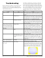
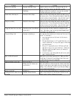
Page 36: ...op of the sprayer tank bypassing all of the sprayer plumbing Venturi will suck but not when the lines are hooked to the spray er or your sprayer lls up before all the product can be sucked from the Ha...

Page 37: ...mproper sealant usage It is important the manufacturers instructions for use are fol lowed As a reminder Store and apply between 20 F and 140 F to clear ta pered threads For pipe diameters up to 1 1 4...

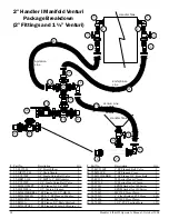
Page 38: ...nge X 1 1 4 MPT 1 7 85 HV150FLA 1 1 2 Venturi Flanged 1 8 25 M200150BRB90 2 SP Flange X 1 1 2 HB 90 2 9 25 M220200CPG 2 FP X 2 SP Flanged Coupler 1 10 25 M220TEE 2 FP Flanged Tee 2 11 25 M220A 2 FP Fl...

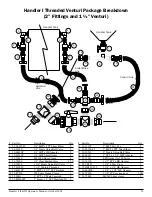
Page 39: ...2 25 M200FPT 2 Flange x 2 FPT Manifold Fit 2 Part No Description Qty 13 10 11105 2 MPT Poly Tee 2 14 25 SL200 45 2 MPT x FPT Stree Elbow 1 15 10 10230 2 Single Union Ball Valve 1 16 49 40013 2 FPT x 1...

Page 40: ...5624 MC24SS Hose Clamp 2 53 75612 MC12SS Hose Clamp 4 53 75632 MC32SS Hose Clamp 4 23 54 79250 2 Kana ex EPDM Ribbed Hose 2 ft 24 54 79210 1 Clear Braided PVC Hose 3 ft 25 54 79050 1 PVC Suction Hose...

Page 41: ...HB100 90 1 MPT X 1 HB 90 2 Part No Description Qty 20 10 10980 1 MPT X 1 MPT 90 1 21 25 SL100 45 1 Street Elbow 45 1 22 10 10910 2 FPT X 1 1 2 HB 90 1 53 75624 MC24SS Hose Clamp 2 25 TC343 TC343 SS S...

Page 42: ...2FRA Handler II frame 1 3 85 HKNIFE Handler kn re 1 4 10 15080 15 polypropylene closed lid 1 5 10 15090G 15 gasketed polypropylene rim 1 6 25 TF100 1 FPT bulkhead 2 Part No Description Qty 7 30 60450...

Page 43: ...Venturi 2 anged berglass lled polypropylene Venturi performance 49 US Gallons minute 41 imperial gallons or 186 liters minute at an operation pressure of 50 PSI NOTE Venturi performance may vary depe...

Page 44: ...llation Handler III 2 Manifold Plumbing Figure H3P 4 1 Thread without using sealant 2 FPT x 2 hose barb 90 degree 10 10930 to anti vortex tting on tank bottom Turn hose barb to desired position and ti...

Page 45: ...bing package See Fig H3P 4 5 Install plumbing assembly to venturi bracket using three 3 8 x 4 U Bolts 67 UB38 400 Tighten all bolts and U Bolts 1 2 3 Figure H3P 4 6 Measure cut and install 1 clear bra...

Page 46: ...ing fresh water does not over ow the Handler tank or spray upwards See Fig H3P 5 1 Repeat this process until the desired amount of chemical has been mixed To drain the Handler tank set valve 1 to rece...

Page 47: ...clogging If more water needs to be added to the tank turn valve 1 to receive fresh water NOTE Repeat above steps until desired amount of mix ture is attained 1 2 3 4 5 6 Once the desired mixture is ac...

Page 48: ...48 Handler I II III Operator s Manual October 2008...

Reviews: