24
Installation
Note
A point to notice
Info.
Supplementary information
Setting the Menus
MAIN MENU
DISPLAY
Sets the display format of the
date and present time on
screen.
TIMER PROGRAM
Sets the timer recording.
RECORDING SET UP
Sets the alarm recording mode,
alarm recording duration, and
emergency recording.
REAR TERMINAL
Sets the frequency division ratio of CLOCK OUT, output
signal of CALL OUT terminal, MODE OUT terminal, etc.
MAINTENANCE
Displays the power loss list, and alarm list, etc. Also,
initializes all menu settings and clears the power loss list and
alarm list.
CLOCK/FIRST TIME SET UP
Sets the present time and the operation at the tape end, etc.
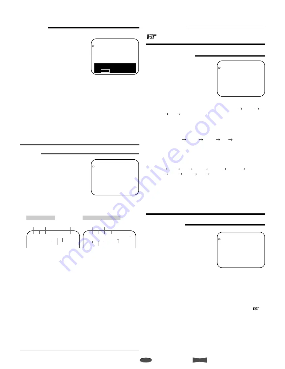
<MAIN MENU>
DISPLAY
TIMER PROGRAM
RECORDING SET UP
REAR TERMINAL
MAINTENANCE
CLOCK/FIRST TIME SET UP
Use JOG to select,
and ENTER.
Press MENU to exit.
DISPLAY
Setting the display mode
(DISPLAY MODE)
1
Shows date and present time.
2
Shows date, day of the week,
present time, and recording
mode.
3
Displays nothing. In case of
alarm recording, same as
DISPLAY MODE 2.
4
Displays nothing.
* shown when DISPLAY MODE 1, 2, or 3 is selected.
Setting the size of letters for date and present time display
(TIME DATE SIZE)
SMALL
The size of the letters become small.
LARGE The size of the letters become large.
Setting the background color (BLUE BACK)
ON
The blue colored screen overlays on the recorded
picture when the menu is displayed on the monitor.
OFF
The blue colored screen will be replaced by the
recorded picture overlaid with the menu display.
•
When the setting is OFF and the video signal is not input,
the blue colored screen overlays on the recorded picture
when the menu is displayed on the monitor.
•
When the setting is ON and the video signal is not input, the
background color will be in blue. In this case, the warning
“NO SIGNAL” flashes on screen and “noSIg” flashes on the
fluorescent display.
<DISPLAY>
DISPLAY MODE
1
TIME DATE SIZE
SMALL
BLUE BACK
ON
e.g.<MODE 1>
07-09-’01 00:00:00
Month
Day
Year
Hour
Alarm
Recording
Counter*
Second
Minute
0 7 - 0 9 - ’ 0 1 2 0 : 2 5 : 0 0 A 0 0 0 1
DISPLAY MODE 1
Month
Day
Day of
the Week
Year
Hour
Alarm
Recording
Counter*
Second
Minute
0 7 - 0 9 - ’ 0 1 M O N A 0 0 0 1
2 0 : 2 5 : 0 0 8
Recording
Mode
DISPLAY MODE 2 and 3
RECORDING SET UP
Setting the alarm recording mode
(ALARM REC MODE)
Sets the alarm recording time
mode.
•
Providing TAPE LENGTH in
FIRST TIME SET UP menu is
set to T-120.
When the JOG dial is turned,
the display will be switched in the order of 6H
L18H
L30H
6H
...
•
Providing TAPE LENGTH in FIRST TIME SET UP menu is
set to T-160.
When the JOG dial is turned, the display will be switched in
the order of 8H
L24H
L40H
8H
...
Setting the alarm recording duration (ALARM REC
DURATION)
Sets the duration of the alarm recording period. When the JOG
dial is turned, the display will be switched in the order of 1M
(minute)
2M
5M
10M
MAN1
MAN2
15S
(second)
30S
45S
1M
...
Setting the emergency recording (EMERGENCY REC)
ON
Starts alarm recording when the ALM IN terminal is
grounded while the VCR is recording, in stop mode,
turned off or in stand-by mode for timer recording.
OFF
Starts alarm recording when the ALM IN terminal is
grounded during recording.
<RECORDING SET UP>
ALARM REC MODE
6H
ALARM REC DURATION
1M
EMERGENCY REC
OFF
TIMER PROGRAM
Page 11, Timer Recording.
REAR TERMINAL
Setting the operation mode of
the CALL OUT terminal (CALL
OUT)
Sets the mode of call signal output
from the CALL OUT terminal. If
any abnormalities occur with the
VCR during recording, the call
signal is output from the CALL OUT
terminal on the rear panel
regardless of CALL OUT setting.
WRNG•TAPE END
The VCR outputs a call signal when the
tape reaches its end during recording or
when a malfunction occurs during
recording. The VCR’s function when the
tape ends depends on the setting of TAPE
END in FIRST TIME SET UP menu (
next page).
WRNG
The VCR outputs a call signal only when a
malfunction occurs during recording.
<REAR TERMINAL>
CALL OUT
WRNG•TAPE END
CLOCK OUT
REC- 1
MODE OUT
REC
REC IN
SERIES


