444 9160 / 444 9180 / 442 9020
39
E 219 GB - Issue 1
10. Monitoring of Safety Devices
Safety Devices:
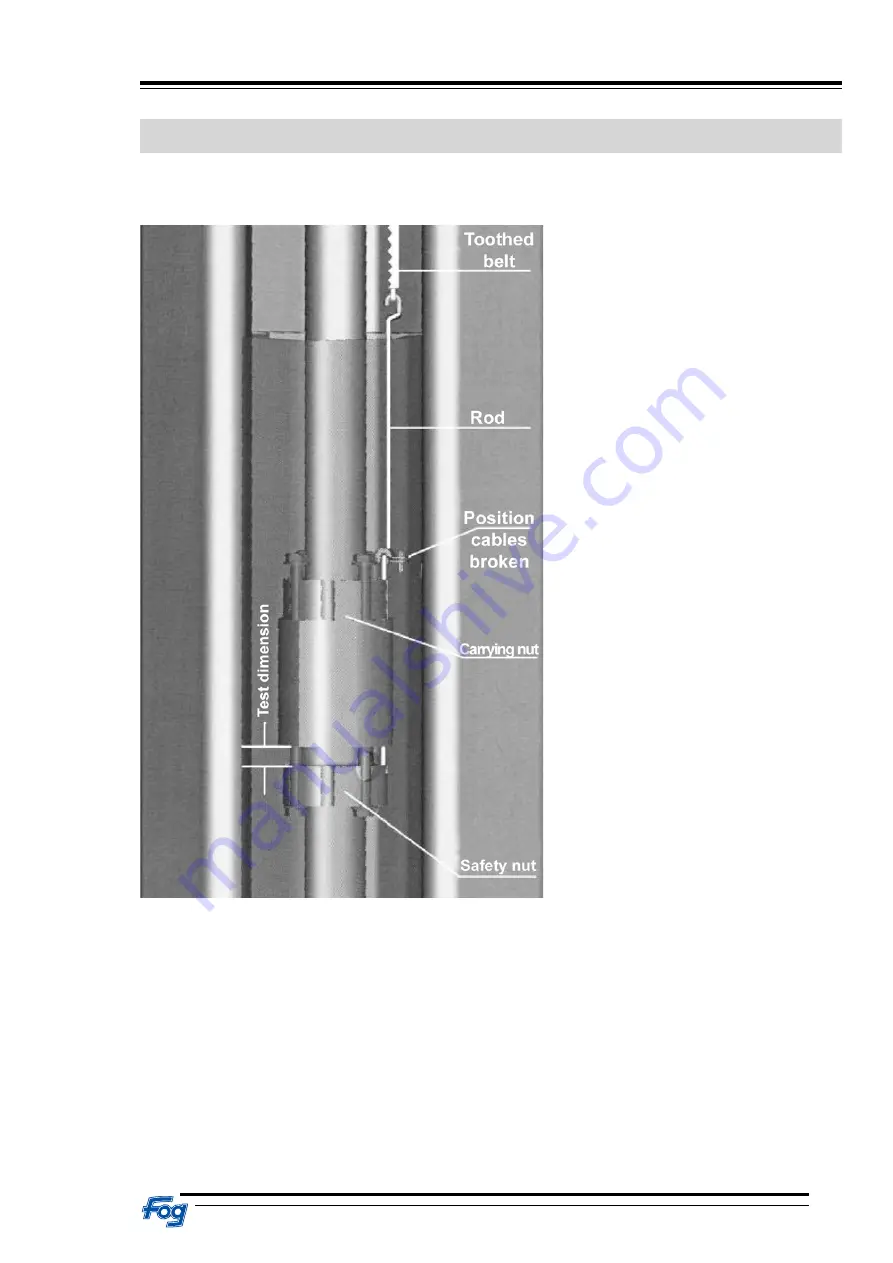
Carrying nut break protection:
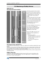
The lift has a protection which sets the lift
out of action if the carrying nut is defective.
Both the carrying nut and the safety nut are
in a protected position within the lifting
carriage and are not accessible from
outside.
During normal operation of the lift the safety
nut runs freely. If the thread of the carrying
nut is worn, the lifting carriage falls onto the
safety nut which has so far run freely and a
rod is pressed out of its anchoring (its
expected breakage point).
At the rod a toothed belt is fixed which runs
over a roller of the analogue path
measuring device (potentiometer) and a
weight is fixed on the other end of the
toothed belt as a counter force.
Because of the different movements, the
analogue path measuring device has
control over :
- The carrying nut break.
- The upper and lower end switch points.
- The exact control of the parallel run of
the lifting carriages.
- The lowering in two steps for foot
protection.
Carrying nut wear and tear test:
To realize the control wear and tear test, it is necessary to take down the spindle cover plate from the column
opening.
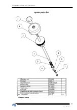
Through the viewing window in the lifting carriage (covered through a vent plug) measure the distance (test
dimension) between the lower edge of the cage ring and the upper edge of the safety nut (figure topside)
by using the feeler caliper or measure by using a measuring gauge.
The distance, if new, is 13,2 mm and may be at minimum 11,2 mm. After that, put the vent plug and install
the spindle cover plate.
Obstacle detection:
The detection is electronically operated, by mean of a power cut-off in case of a slowing down in the
movement, or in the event of a level difference. Due to risks of deterioration, it is advised not to test this
device when servicing / maintaining the lift.
Summary of Contents for 442 9020
Page 13: ...444 9160 444 9180 442 9020 13 E 219 GB Issue 1 ...
Page 14: ...444 9160 444 9180 442 9020 E 219 GB Issue 1 14 ...
Page 15: ...444 9160 444 9180 442 9020 15 E 219 GB Issue 1 ...
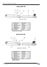
Page 17: ...444 9160 444 9180 442 9020 17 E 219 GB Issue 1 Lifting arms for type 442 9020 ...
Page 21: ...444 9160 444 9180 442 9020 21 E 219 GB Issue 1 ...
Page 23: ...444 9160 444 9180 442 9020 23 E 219 GB Issue 1 ...
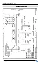
Page 42: ...444 9160 444 9180 442 9020 E 219 GB Issue 1 42 13 Electrical diagrams ...
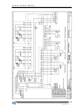
Page 43: ...444 9160 444 9180 442 9020 43 E 219 GB Issue 1 ...
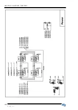
Page 44: ...444 9160 444 9180 442 9020 E 219 GB Issue 1 44 ...
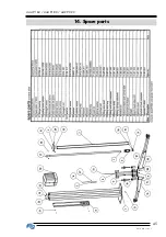
Page 45: ...444 9160 444 9180 442 9020 45 E 219 GB Issue 1 14 Spare parts ...
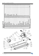
Page 46: ...444 9160 444 9180 442 9020 E 219 GB Issue 1 46 ...
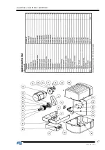
Page 47: ...444 9160 444 9180 442 9020 47 E 219 GB Issue 1 ...
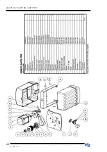
Page 48: ...444 9160 444 9180 442 9020 E 219 GB Issue 1 48 ...
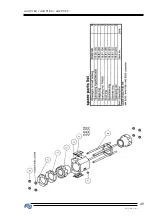
Page 49: ...444 9160 444 9180 442 9020 49 E 219 GB Issue 1 ...
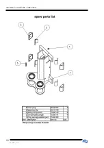
Page 50: ...444 9160 444 9180 442 9020 E 219 GB Issue 1 50 ...
Page 51: ...444 9160 444 9180 442 9020 51 E 219 GB Issue 1 ...
Page 52: ...444 9160 444 9180 442 9020 E 219 GB Issue 1 52 ...
Page 53: ...444 9160 444 9180 442 9020 53 E 219 GB Issue 1 ...
Page 54: ...444 9160 444 9180 442 9020 E 219 GB Issue 1 54 ...
Page 55: ...444 9160 444 9180 442 9020 55 E 219 GB Issue 1 ...
Page 56: ...444 9160 444 9180 442 9020 E 219 GB Issue 1 56 ...
Page 57: ...444 9160 444 9180 442 9020 57 E 219 GB Issue 1 ...
Page 58: ...444 9160 444 9180 442 9020 E 219 GB Issue 1 58 ...
Page 59: ...444 9160 444 9180 442 9020 59 E 219 GB Issue 1 ...
Page 60: ...444 9160 444 9180 442 9020 E 219 GB Issue 1 60 ...
Page 70: ...444 9160 444 9180 442 9020 E 219 GB Issue 1 70 ...
Page 71: ...444 9160 444 9180 442 9020 71 E 219 GB Issue 1 ...


