background image

10

6-1. 

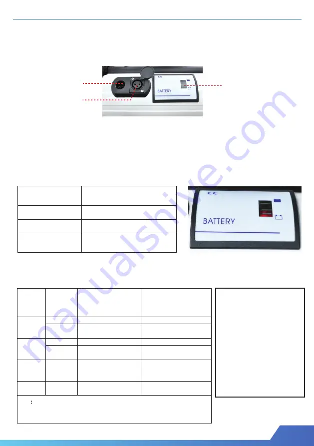
Battery and Control Box Connection

The main electrical control system is composed of the motor, Control box battery
 and controller. 
Connect the power cord of the control box to the battery. 

6-2. 

Battery Charge

The buzzer for Battery Capacity and Controller

1. First connect the battery charge cord to the battery DC power socket,
     make sure the cord is properly connected . 
2. Connect the AC power cord of the charger to the AC socket. (100~240V)
3. The light of battery charger changes from yellow to green represent
     the battery charge is complete.

6.0 CONTROL SYSTEM

Battery capacity 

indictor color 

Power condition 

Green 


Yellow 


Red 


* When the battery power is empty power, it will stop working.

Battery 

power 

indicator 

color 


Battery 

Capacity 


Controller 


Sound of buzzer 


Green 

Full power 

Switch ON


Sound 1 times 

Full power 

Switch OFF          


Not using over 30 min


Yellow 

Half power


Switch ON 

Short sound 1 times 

Half power


Switch OFF           

Not using over 30 min


Control mode


Switch can only 

Push 

downward

    (Safety mode) 

Sound continue when using 


Red


Empty power


Shut down


Must charge immediately


Note


If the motor stops working, but the chair still in standing position, please use battery charger.

about 5 min


Attention :

1. Check the battery 
     capacity weekly.
2. New battery must charged
    over 8 hours.
3. Charge your battery from the 
     battery charger provided by
     manufacturer only.  

Battery Capacity 
Indicator

DC Power Socket

Charging Socket

Full Power

Half Power

Low Power

-

-

No light

Low power

Battery life.

(about 5 minutes) . The chair can slowly sit down. Do not do it oftenly, It will reduce the 

Summary of Contents for PEGASUS II

Page 1: ...V2 0 User Manual PEGASUS II...

Page 2: ...peration 08 5 0 Storage 09 6 0 Control System 10 7 0 Maintenance 11 Contact Us 11 01 Backrest 02 Handle Controller 03 Rear Wheel 04 Handrim 05 Wheel Lock 06 Gas Spring 07 Quick release Fork 08 Caster...

Page 3: ...parts not supplied by technical personnel may change the wheelchair structure and create an unsafe condition thus voiding the warranty 1 4 Modifications 1 3 Rear Wheel 1 3 1 Quick Release Axles Check...

Page 4: ...the frame and voids the warranty 1 5 Armrests 1 6 Power Drive Attachments Armrests Standing wheelchair heel strap safety belt chest belt Knee support and charger User manual and tool Options as order...

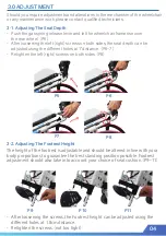
Page 5: ...e different holes at 1 distance P6 7 Retighten the left right screws on both sides P8 The height of the footrest is adjustable and should be altered in line with your body proportions to guarantee the...

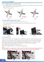
Page 6: ...ing The Backrest Height 3 4 Wheel Lock Remove the backrest pad and end cap P15 16 After opening both screws left right the backrest height can be adjusted P17 Retighten the screws The manual brakes ar...

Page 7: ...ular clasp of the knee lock support to the double head screws on either side of the wheelchair P20 Center the knee support in front of each knee using the Velcro fasteners then pull it until it is sit...

Page 8: ...elcro at the back of the backrest The chest belt is to hold the upper body chest in place P24 P25 P26 3 5 3 The Safety Belt The safety belt holds the waist in place Make sure that the safety belt is s...

Page 9: ...hest belt It is absolutely essential that these be correctly in place before you attempt to stand up Standing up stresses your body in ways you may not be used to For this reason please consult your d...

Page 10: ...can fold the backrest P30 32 5 2 The Quick release Axles The quick release axles enable you to remove and re mount the rear wheel of your Pegasus II thus reducing significantly the volume and weight...

Page 11: ...p working Battery power indicator color Battery Capacity Controller Sound of buzzer Green Full power Switch ON Sound 1 times Full power Switch OFF Not using over 30 min Yellow Half power Switch ON Sho...

Page 12: ...ure between once a week and once a month If necessary pump the tyres in line with manufacturer s recommendations Check the state of the tread on the tyres every one to six months If a tyre is heavily...

Reviews: