background image


FGI-011_Rev.D  08/10/2015                                                                                                          Qwik-Fence Installation Instructions                                                                                                                                        

Toll Free: (800) 622-2214 
Phone: (708) 325-0400 
Fax: (708) 325-0450 

5858 W. 73

RD

 ST 

BEDFORD PARK, IL.  60638 

Qwik-Fence

®


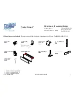
Brackets & Assemblies 

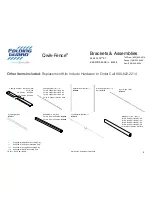
Other Items Included: 

Replacement Kits Include Hardware to Order Call 800-622-2214 

Panel Clip   (B1) 

KT0201 

Hinge Door Header  
Bracket   (B3)* 

KT0203 

Floor Bracket (B2) 

KT0202 

Slide Door Mounting Strip   
(B5)** 

KT0205 

Slide Door Bracket (B4)** 

KT0204 

Slide Door Bottom Guide  

Slide Door Guide (B8) ** 

KT0207 

Mesh Clamp (B10)*** 

KT0209 

Supplied for Hinge Door Assembly Only 

** 

Supplied for Slide Door Assembly Only 

*** 

Supplied for Ceiling Kit Assembly Only 

****  Supplied for Wall Kit Assembly Only 

Slide Door Trolley  
Assembly (B9) ** 

KT0208 

Summary of Contents for Qwik-Fence

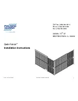
Page 1: ...FGI 011_Rev D 08 10 2015 Qwik Fence Installation Instructions Toll Free 800 622 2214 Phone 708 325 0400 Fax 708 325 0450 5858 W 73RD ST BEDFORD PARK IL 60638 Qwik Fence Installation Instructions 1...

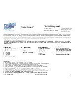
Page 2: ...nry Bit 5 16 Masonry Bit 5 16 Wrench 7 16 Wrench 9 16 Wrench Hammer Electric Drill Var Speed Tools Recommended Ladder Carpenters Level Chalk Line Heavy Duty Wire cutters Tools Recommended Shims NOT SU...

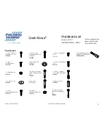
Page 3: ...207 14 X 1 Slotted Head Screw F5 KT31149 14 X 1 TEK Self Tapping Screw F6 Optional KT31825 3 8 x1 Washer F7 Optional KT33008 3 8 16 X 3 75 Concrete Anchor Slide Door Option F8 KT52205 1 2 20 x 3 3 4 F...

Page 4: ...dware to Order Call 800 622 2214 Panel Clip B1 KT0201 Hinge Door Header Bracket B3 KT0203 Floor Bracket B2 KT0202 Slide Door Mounting Strip B5 KT0205 Slide Door Bracket B4 KT0204 Slide Door Bottom Gui...

Page 5: ...Wall Kit Assembly Only Capping Channel Optional M3 Var Sizes 48 Part No QFCC 48 96 Part No QFCC 96 Ceiling Angle Kit C1 For 3 w support Part No CA3 For 4 w support Part No CA4 For 8 w support Part No...

Page 6: ...RD ST BEDFORD PARK IL 60638 Qwik Fence 6 Planning Layout Fig 1 1 Capping Channel M3 Optional See Step 10 for installation directions Panel M1 Post M2 NOTE 2 Sweep Space Panel 8 X4 Nominal M1 Standard...

Page 7: ...Kit Angle W1 to the existing wall with provided Slotted Head Screw F5 and Plastic Anchor F6 See Figure 2 2 for refer ence Attach the Wire Mesh Panel When attaching the Wire Mesh Panel M1 DO NOT FORGE...

Page 8: ...step See Figure 3 1 for reference The lower panel should be approximately two 2 o the ground for Standard Installa on If you have a ver cal post M2 with a 2 X6 base you may use that post as a spacer b...

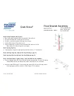
Page 9: ...c Anchor F13 Refer to Figure 6 1 for reference Fig 6 1 Step 7 Adjusting Panel Size If size adjustment is required using heavy duty wire cutters cut every 1 horizontal wire Step 8 Installing a Hinge Do...

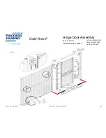
Page 10: ...Instructions Toll Free 800 622 2214 Phone 708 325 0400 Fax 708 325 0450 5858 W 73RD ST BEDFORD PARK IL 60638 Qwik Fence 10 Hinge Door Assembly Fig 8 1 DOOR POSTS SPACING DOOR H3 37 25 94 54cm inside...

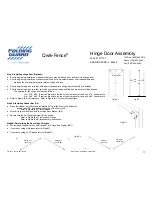
Page 11: ...ground to the top of the clearance for the door 37 5 header width H4 49 5 X 96 From the ground to the top of the clearance for the door 49 5 header width Refer to Figure 8 2 for reference Refer to Fig...

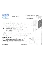
Page 12: ...Figure 8D 1 Make sure that the top and bottom of the Stop Angle D3 are approximately lined up with the top and bottom of the door Fig 8E 1 Step 8E Installing Door Attach the Door to the Hinge post Bas...

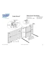
Page 13: ...W 73RD ST BEDFORD PARK IL 60638 Qwik Fence 13 Slide Door Assembly Toll Free 800 622 2214 Phone 708 325 0400 Fax 708 325 0450 DOOR POSTS 36 INSIDE OF POSTS FOR S3 48 INSIDE OF POSTS FOR S4 60 INSIDE O...

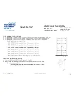
Page 14: ...S3 36 X 96 From the ground to the top of the clearance for the door S4 48 X 96 From the ground to the top of the clearance for the door S5 60 X 96 From the ground to the top of the clearance for the...

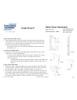
Page 15: ...nimal If your Ver cal Post height is taller then 96 DO NOT a ach the Slide Door Bracket B4 to the Slide Door Moun ng Strip B5 Instead Measure 96 from the ground to the bo om of the Slide Door Bracket...

Page 16: ...e mesh panel M1 Please go on the next point If you intend to secure the Guide B6 to the floor secure together via floor anchors as shown in Figure 9F 2 If a aching the Bo om guide to the wire mesh ass...

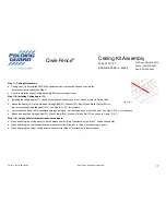
Page 17: ...Attach the Angle C1 via the provided Carriage Bolt F2 Washer F4 Nut F3 and Mesh Clamp B10 to the vertical already installed panel M1 See Figure 11A 1 for reference Lay in the Mesh Panel M1 horizontall...

Reviews: