8
Operation
The temperature control board and probe indicate when the refrigeration system is required to turn on and off.
The refrigeration system removes heat from the cabinet interior and rejects it to the surrounding room air. When the
cabinet interior temperature reaches 4 F above the controller set point, the probe signals the controller to turn the
refrigeration system on. The normally open controller contacts close and energize the evaporator and condenser
fan motors and compressor. The compressor uses a current-style starting relay and a starting capacitor to start the
compressor motor.
When the cabinet interior temperature falls to the set point, the probe signals the controller to turn the refrigeration
system off. The controller contacts reopen, which de-energizes the evaporator and condenser fan motors and the
compressor.
Any accumulated frost on the evaporator coils melts during the off cycle. The condensate drains to a plastic drain
pan mounted above the condensing unit. The heat from the condensing unit evaporates any condensate in the
drain pan.
Temperature control
The temperature control system is preset by the factory to maintain a cabinet temperature of 34 F – 38 F. If desired,
the cut-out temperature can be raised as high as 42 F by following the instructions on page 6 for changing the
temperature set point. The 4 F cut-out differential will be maintained regardless of the controller set point.
Defrosting
REF Series undercounter refrigerators do not require manual defrosting. The unit cooler defrosts automatically
when the condensing unit is in the OFF cycle.
Cleaning
Interior – Using a sponge or soft cloth, clean unit with a non-abrasive, non-chlorinated, all-purpose detergent.
Exterior – Wipe exterior with a soft cloth in the direction of grain as needed. Stainless steel polish may be used to
enhance the fi nish of the unit.
Annual cleaning
Removal of dust and other particulates from air intake areas and the condenser is important for proper operation.
Some environments with large amounts of dust may require more frequent cleaning.
1. Disconnect power to unit by turning switch on the lower
front panel to the OFF position, switching circuit breaker to
OFF position, and removing power cord from receptacle.
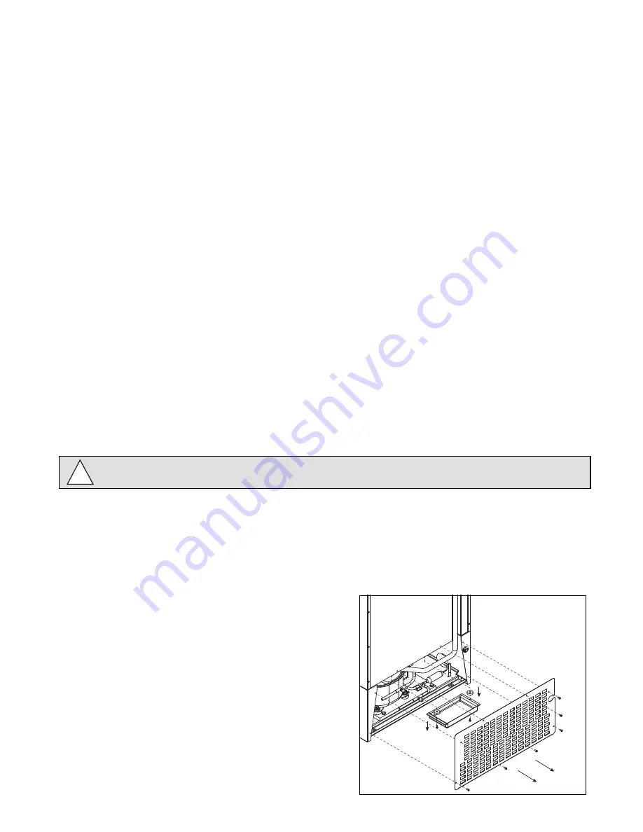
2. Remove lower front and rear panels (Fig. 9.1).
Note:
Front louvered panel may be removed for more
frequent cleaning of the condenser as needed
3. Remove drain pan (Fig. 9.2).
4. Clean drain pan with a non-abrasive, non-chlorinated all-
purpose detergent.
5. Reinstall drain pan.
6. Use a vacuum cleaner with brush attachment to clean
condenser through lower front panel and compressor
motor and related parts through lower rear panel.
7. Reinstall lower rear and lower front panels.
1
2
Fig. 9
Use only non-chlorine-based cleaners. Cleaners containing chlorine can cause staining and pitting of the
stainless steel.
!


