16
12CI400A • 12HI400A
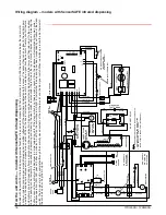
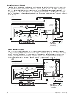
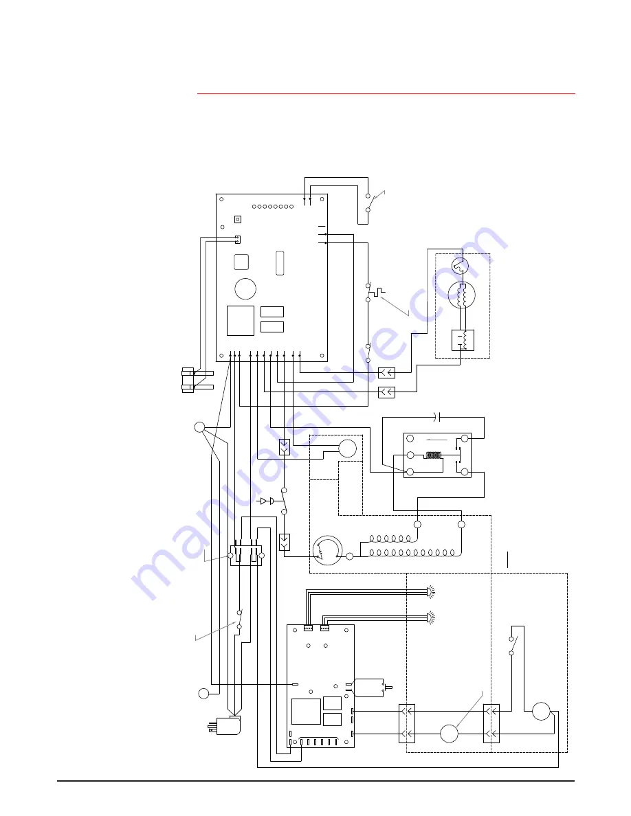
Wiring diagram – models with SensorSAFE infrared dispensing
Ho
w the unit w
or
ks — models with SensorS
AFE infr
ar
ed dispensing
Models with SensorS
AFE infr
ar
ed dispensing pr
ovide
“t
ouchless”
ice and w
at
er dispensing
. W
hen a cont
ainer is placed within the actuation z
one belo
w the ice or w
at
er
chut
e, an in
visib
le
, r
andoml
y-gener
at
ed infr
ar
ed signal is emit
ted, r
efl
ect
ed of
f the cont
ainer and det
ect
ed b
y the sensor
. The sensor then sends a signal t
o the contr
ol boar
d
to activ
at
e the appr
opr
iat
e components t
o dispense ice or w
at
er
. LEDs on the boar
d indicat
e when the boar
d is r
eceiving a signal fr
om the sensor
s.
A saf
et
y, shut-of
f f
eatur
e
aut
omaticall
y shuts of
f dispensing af
ter one min
ut
e of contin
uous activ
ation.
Dispensing can be r
est
ar
ted b
y mo
ving the cont
ainer a
w
ay and then r
etur
ning it t
o the actuation
zone
. Dispensing can be t
empor
ar
ily suspended b
y depr
essing and r
eleasing the clean s
witch, locat
ed under the lef
t side of the t
op fr
ont co
ver
. Depr
essing and r
eleasing the
but
ton a second time will r
etur
n the dispenser t
o nor
mal oper
ating st
at
e.
If the clean s
witch is not depr
essed a second time
, the dispenser will aut
omaticall
y r
esume nor
mal
dispense oper
ation (CLN
LED goes out) af
ter t
w
o min
ut
es
. An LED on the contr
ol boar
d will light t
o indicat
e that the dispensing has been suspended b
y activ
ation of the clean
switch.
The bin signal cir
cuit is complet
ed thr
ough the nor
mall
y closed cont
acts of the bin ther
most
at and the bin signal s
witch.
W
hen ice b
uilds up ar
ound the bin ther
most
at,
the cont
acts open, cut
ting the bin signal.
801 Church Lane Easton, PA 18040 USA For service call: Toll free (877) 612-5086 or +1 (610) 252-7301 On the web: www.follettice.com
208580R05
12 Series with SensorSAFE
SOL
WTR
NEUTRAL
CLN
WM
PWR
WTR
L1
GND
ICE
COMM.
SWITCH
COMP .
MOUNTED ON
W
ATER
COMPRESSOR
WHITE #34
BLA
CK #41
WHEELMO
TOR
M
COMPONENTS
MOUNTED ON MAIN FRAME
BLA
CK #33
1
SOLENOID
4
SPLA
SH P
ANEL
COMP
. S
TAR
T RELA
Y
#37
WHITE
S
#36
BLACK
BLACK #25
STA
RT
BLACK
BLACK #35
COMPONENTS
SENSOR
W
ATER
SENSOR
ICE
CLEAN SWI
TCH
ORANGE #23
R
RUN
BLACK
S
L
S
UP
M
1
2
#40
#40
YELLO
W
YELLO
W
BLACK #24
4
1
MAIN FRAME
BLA
CK #22
COMPRESSOR O
VER-L
O
AD
COMPONENTS MOUNTED ON
(INTERNAL)
C
WHITE #1
6
FA
N
#42
S
TA
R
T
S
TA
R
T
RELA
Y
COMP . S
T AR
T
CAP
ACI
TOR
BLA
CK
YELL
O
W
MOUNTED ON MAIN FRAME
#42
3
4
2
RU
N
WHITE
BLUE
GEAR MO
TOR
BLA
CK #1
9
BLA
CK #1
8
BLACK #20
WHITE #1
5
WHITE #1
7
BLACK #1
4
RED #20
24
LINE
VAC
VAC
RED #20
GREEN #1
2
RED #46
11
5 V
A
C
GREEN
WHI
TE #44
BLA
CK #43
WHI
TE #26
WHI
TE
BLA
CK
BLA
CK #1
3
HIGH PRESSURE S
AFETY SWI
TCH
RED
#21
8
4
7
3
6
2
5
1
WHI
TE #1
1
BLA
CK #1
0
GREEN #45
GREEN #27
TERMINAL BL
OCK
x
LABEL
I.D
.
I.D
.
SOF
TW
ARE
COMP
.
FA
N
DRIVE
L2
L2
EAR
TH
L2
L2
L2
L1 L1
B-E
B-T
WTR
60M
2ND
SENSOR
C
20M
DR
W
ATER
RESET
PO
WER
GRN T
O
MAIN FRAME
x
GRN IN ELEC
. BO
X
W
ATER SENSOR
PO
WER SWI
TCH
1.
COMPRESSOR S
TAR
T RELA
Y IS GRA
VI
TY SENSI
TIVE.
SEE LABEL FOR PR
OPER ORIENT
ATION
NO
TE
CL
OSED COMP
. OFF)
(OPEN COMP
. ON,
COMPRESSOR SWI
TCH
BIN
LEVEL THERMOS
TA
T
BIN SIGNAL SWI
TCH
OPEN:
425psi CL
OSES:
297psi (A
UT
ORESET)
2.
HIGH PRESSURE S
AFETY SWI
TCH:
T.O
.L.
60 HZ


