Accessories
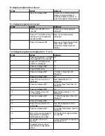
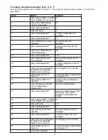
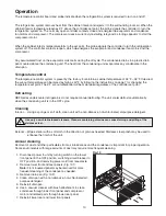
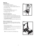
Temperature alarm
Before installing alarm
1. Remove supplied 9-volt back-up battery from packing
box.
2. Remove 2 screws from module face and remove
faceplate.
3. Install back-up battery on battery connector.
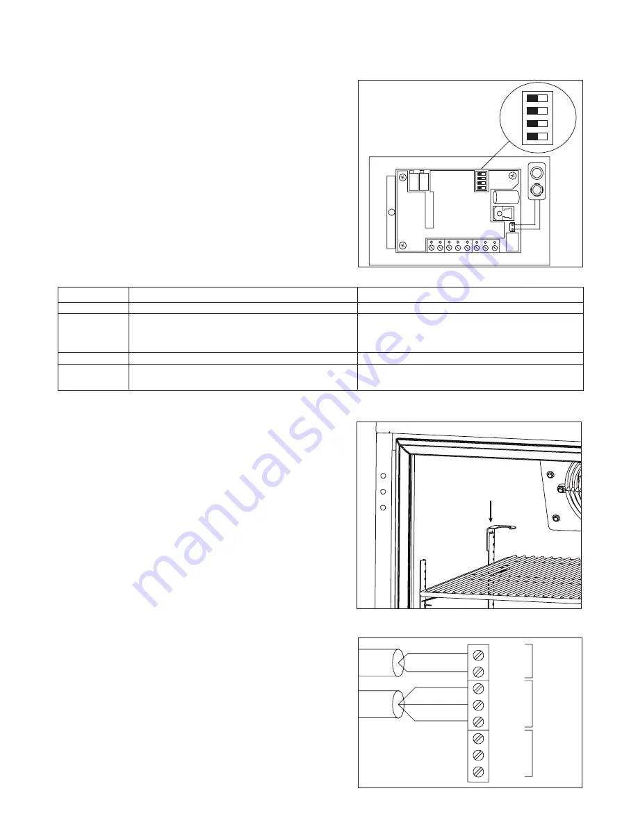
4. Locate DIP switches on the back of the faceplate
(Fig. 13).
5. Review the factory DIP switch settings (Fig. 14) and
make any changes required to meet the needs of your
specific application.
6. Reinstall faceplate.
Dip Switch
OFF (factory default setting)
ON
1
No alarm delay
45 minute alarm delay
2
Auto reset (alarm stops automatically as
Manual reset of alarm (user must press
soon as temperature returns to set range)
RESET button to stop audible alarm even if
temperature has returned to set range)
3 & 4
Audible alarm on (no snooze with both off)
No audible alarm
3
Enables 5 min alarm “snooze”
Enables 45 min alarm “snooze”
when reset button is pressed (3 off with 4 on)
when reset button is pressed (3 on with 4 off)
Fig. 14
Fig. 15
Installing alarm
1. Mount alarm in desired location with screws (supplied
by others) through back of housing. Do not place
undue strain on probe cable.
Note:
Do not modify length of probe wire. Probe will
not measure temperature correctly if wire length is
changed.
2. Plug power cord into 110 outlet.
3. Push center tab of short bottle bracket into top of rear
left pilaster (Fig. 15).
Note:
Use longer bottle bracket for REF5 refrigerators
using cut-out upper shelf accessory.
4. Fill bottle with glycerin or other liquid to increase
accuracy of readings by simulating the internal
temperature of medications.
5. Insert bottle into bottle bracket.
6. Route probe through hole in refrigerator back and push
probe down through gasketed bottle top.
Note:
Alarm probe must be placed in bottle for
proper system operation. Refer to Fig. 16 if attaching
alarm to central monitoring or central alarm system. A
SPDT 1 amp 24V AC resistive relay is provided for this
connection.
15
OFF
OFF
OFF
OFF
POWER SENSOR OUTPUT
Fig. 13
AC
AC
Black
White
Red
NC
NO
Com
Output
Sensor
Power
in
Fig. 16

