12
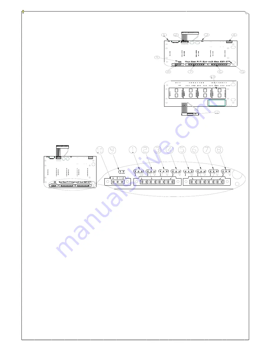
(Fig. 14) Voltage/current proportional
output module
(6) Voltage/Current Proportional Output Module
1. Status LED
2. ” LCD Display” Connector
3. RESET Status LED
4. External Power Input
5.
Joystick/VR Output Voltage & Current Setting JUMPER
6.
Joystick 5/VR5 ~ Joystick 8/VR8 Voltage & Current Output
7.
Joystick 1/VR1 ~ Joystick 4/VR4 Voltage & Current output
8. RS485 Output Interface (optional)
9. RS485 Terminal Resistance Setting JUMPER
10.Proportional Output Module Card
11.Output Module to Decoder Card Connecting Port
①
~
⑧
Corresponding joystick 1/VR1 ~ joystick 8/VR8
* Plug short pin into the 3-pin JUMPER left (“I” mark): Select “current” output and plug short pin into the 3-pin
JUMPER right (“V” mark): Select “voltage” output
。
Current output:
Software setting(0~20mA
、
0~24mA & 4~20mA available) and plug the short pin into the 3-pin
JUMPER left.(“I” mark)
Voltage output:
Software setting (0~+5V
、
0~+10V
、
0~±5V & 0~±10V available) and plug the short pin into
the 3-pin JUMPER right.(“V” mark)
* Each joystick/VR corresponds to the 2-pin output terminal. Left terminal is for voltage/current output and right
terminal is for GND.
⑨
RS485 output terminal with 150Ω resistance. Plug in short pin: Use terminal resistance; not using short pin: Not
using terminal resistance.
⑩
RS485 output


