


- 13 -
16
19
18
17
15
5
11
12
10
8
9
7
1
3
4
2
14
6
13
4
4
.
.
2
2
.
.
2
2
A
A
l
l
p
p
h
h
a
a
6
6
1
1
2
2
I
I
n
n
t
t
e
e
r
r
n
n
a
a
l
l
A
A
s
s
s
s
e
e
m
m
b
b
l
l
y
y
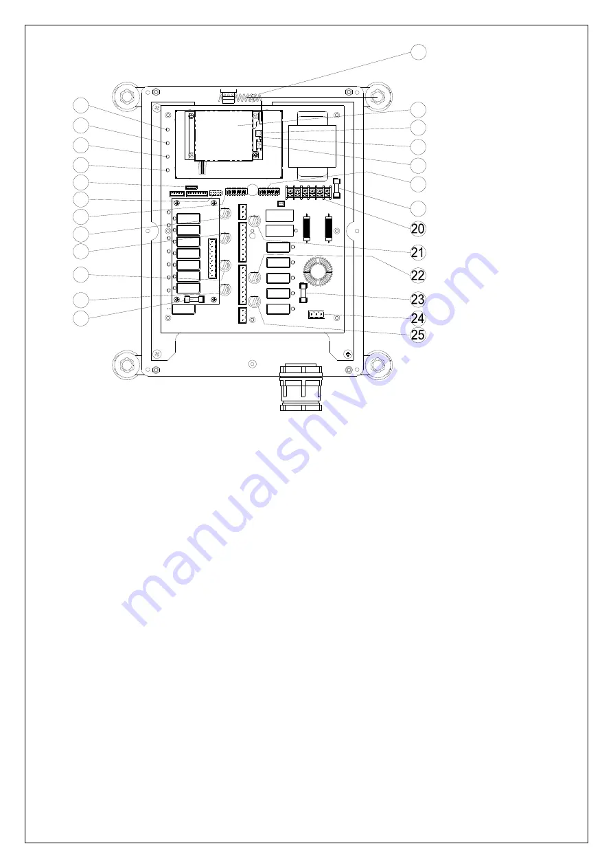
(Fig. 10) Internal Parts Assembly
1)
Power LED display*
13) Internal Antenna
2)
SQ LED display**
14)
Receiving RF module
3)
Status LED display****
15) External antenna port
4)
DC power relay LED display***
16) Receiving RF module red status light
5)
Programming port
17) Transmitter pairing button
6)
Jumper settings
18) ID code dip-switch
7)
Function dip-switch
19)
Secondary power fuse F1*
(refer to power fuse list 4.3)
8)
Pushbutton #3 and #4 relay fuse (5.0A)
20) Voltage selector seat
9)
Pushbutton #5 and #6 relay fuse (5.0A)
21) MAIN relay fuse (5.0A)
10) Pushbutton A1and A2 relay fuse (5.0A)
22) Pushbutton A4 relay fuse (5.0A)
11) Pushbutton A3 relay fuse (5.0A)
23)
Primary power fuse FF1*
(refer to power fuse list 4.3)
12) Pushbutton #1 and #2 relay fuse (5.0A)
24) Power port CN2
25) Low-voltage (LV) relay fuse (5A)
*
POWER
~ AC Power Source Indicator "on"
→
AC input power supplied.
"off"
→
No AC input power.
**
SQ
~ RF Signal Indicator "on"
→
RF signal detected and received.
"off"
→
No RF signal detected or received.
Blinking at transmitt
er power “off”
→
Other radio interference.
***
RELAY_COM
~ DC Power Source to Relays "on"
→
DC power to relays.
"off"
→
No DC power to relays.
****
STATUS
~ Receiver System Status LED Display
→
Please refer to page
39.
Summary of Contents for Alpha 600XJ Series
Page 19: ... 18 STOP POWER PB1 PB2 PB4 PB3 PB5 PB6 PB8 PB7 PB9 I II Alpha 612BJ ...
Page 20: ... 19 STOP POWER PB1 PB2 PB4 PB3 PB5 PB6 PB8 PB7 PB9 Alpha 612C 1J ...
Page 21: ... 20 STOP POWER PB1 PB2 PB4 PB3 PB5 PB6 PB8 PB7 PB9 Alpha612C 2J ...
Page 22: ... 21 STOP POWER PB1 PB2 PB4 PB3 PB5 PB6 PB8 PB7 PB9 Alpha 612DJ ...
Page 23: ... 22 STOP POWER PB1 PB2 PB4 PB3 PB5 PB6 PB8 PB7 PB9 I II Alpha 612E 1J ...
Page 24: ... 23 STOP POWER PB1 PB2 PB4 PB3 PB5 PB6 PB8 PB7 PB9 I II Alpha 612E 2J ...


