- 39 -
2 5 5 mm
2 7 8 mm
4 - O10.5
9.2.2 Commissioning steps
1. Decide the wiring type and cable. If the cable gland is used for the cable, please use the enclosed
rubber cork to seal the cable gland without cable.
2. For system wiring, please refer to the output contact diagrams from page 13.
3. Ensure the selected location has adequate space to accommodate the receiver enclosure.
4. Make sure the receiver unit is in upright position (vertical).
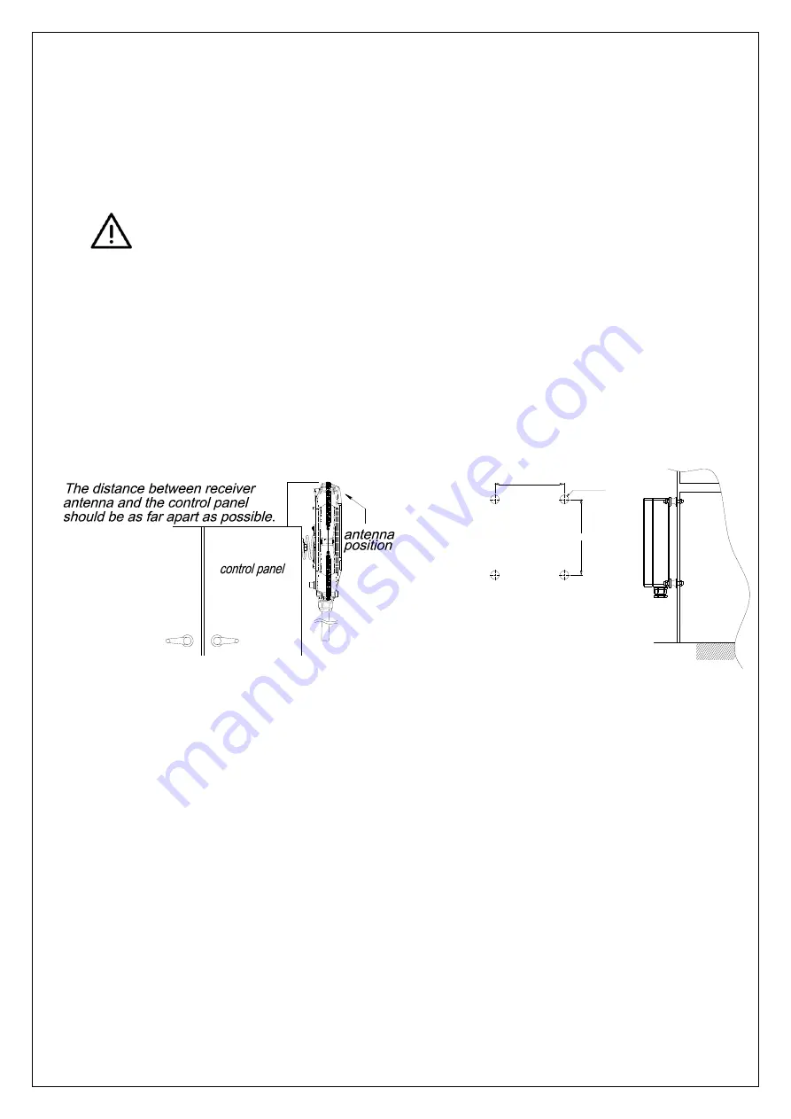
The distance between the antenna and the control panel should be as far apart as
possible.
(refer to the fig.11 & 12).
5.
If a crane or equipment’s runway is longer than 100 meters, an external antenna should be added.
The Alpha 608 receiver housing has provisions for an external factory installed antenna available as an
option, contact your dealer for price and delivery.
6. Drill a hole on the control panel (10.5mm).
7. Tightened the bolt nuts provided.
8. If the control panel has a plastic surface, extended grounding wire should be used.
9. Ensure all wiring is correct and safely secured and all screws are fastened.
9
9
.
.
3
3
S
S
y
y
s
s
t
t
e
e
m
m
T
T
e
e
s
s
t
t
i
i
n
n
g
g
1.
Connect the power source to the receiver and test the MAIN relay output by pressing the red
emergency stop button (EMS) and observe that it properly opens and closes the main line
disconnect contactor.
2.
Test the operation of each function to ensure it corresponds to the transmitter direction labels and/or
the pendant it is replacing.
3.
Test the limit switches on the hoist and/or crane and verify they are working properly.
4.
If your new remote control is replacing an existing pendant, make sure it is completely
disconnected to prevent unwanted control commands, i.e. snick circuits.
5.
If your new remote control is replacing an existing pendant make sure it is stored in a safe location
where it will not interfere with remote operation (get torn off).
(Fig.11) Alpha 604, 607,
608 Models
(Fig.12) Alpha 612 Models
Summary of Contents for Alpha 600XJ Series
Page 19: ... 18 STOP POWER PB1 PB2 PB4 PB3 PB5 PB6 PB8 PB7 PB9 I II Alpha 612BJ ...
Page 20: ... 19 STOP POWER PB1 PB2 PB4 PB3 PB5 PB6 PB8 PB7 PB9 Alpha 612C 1J ...
Page 21: ... 20 STOP POWER PB1 PB2 PB4 PB3 PB5 PB6 PB8 PB7 PB9 Alpha612C 2J ...
Page 22: ... 21 STOP POWER PB1 PB2 PB4 PB3 PB5 PB6 PB8 PB7 PB9 Alpha 612DJ ...
Page 23: ... 22 STOP POWER PB1 PB2 PB4 PB3 PB5 PB6 PB8 PB7 PB9 I II Alpha 612E 1J ...
Page 24: ... 23 STOP POWER PB1 PB2 PB4 PB3 PB5 PB6 PB8 PB7 PB9 I II Alpha 612E 2J ...


