background image


- 45 - 


1

1

2

2

.

.


S

S

Y

Y

S

S

T

T

E

E

M

M


S

S

P

P

E

E

C

C

I

I

F

F

I

I

C

C

A

A

T

T

I

I

O

O

N

N


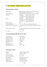
Transmitter Unit 


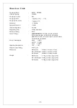
Transmitting RF Board Unit 


Charger Unit 


Source Voltage 

Ni-MH AA size x 2 batteries 2.4V (no contact charging) 
Or AA size alkaline x 2 batteries 3.0V   

Antenna Impedance 

Internal Antenna 50 ohms. External antenna is available. 

Dimension 

604 Models        : 140mm x 68mm x 30mm 


607, 608 Models: 189mm x 68mm x 30mm 


612 Models        : 235mm x 68mm x 30mm 

Weight 


604 Models        : 220g (include batteries) 


607, 608 Models: 280g (include batteries) 


612 Models        : 350g (include batteries) 

Enclosure Rating 


IP-66 

Operating Temperature 


-10 ~ +60

(> 80

  high temperature protection ) 

Transmitting Power Consumption  : 

20mA@3V (Various from encoding mode and transmitting 

power)


Continue Operating Time 

> consecutive 80hrs @batteries full (2000mA), Transmitting 
Power 10mW 

Low Voltage   

2.2V 

 1.8V   

Frequency Range 

902~928 MHz 

Transmitting Power 

1 mW 

 100mW 

Frequency Control 

TCXO + PLL 

Frequency Deviation 

2ppm @ 25


Spurious Emission 

< - 50dBc. 

Emission   

F1D 

Antenna Impedance 


50 ohms 

Operating Temperature 


-10

  ~ +60


Dimension 

120mm x 105mm x 105mm 

Voltage 

100~240V 50/60Hz 

Power Consumption 

Max.10 Watt 

Operating Temperature 


0

~ +40


Heat Ventilation 

Temperature Control Fan 

Charging Current 

About 600mA @3V 

Charging Time 

About 3hrs @2000mAh 

Charging Detection 

-

Δ

V + Temperature 

Summary of Contents for Alpha 600XJ Series

Page 1: ... S Se er ri ie es s I I n n d d u u s s t t r r i i a a l l R R a a d d i i o o R R e e m m o o t t e e C C o o n n t t r r o o l l S S y y s s t t e e m m O Op pe er ra at ti io on n P Pa ar rt ts s M Ma an nu ua al l Fomotech International Corp ...

Page 2: ...s 15 5 3 Alpha 608 Models 16 5 4 Alpha 612 Models 17 6 SYSTEM CONFIGURATIONS 6 1 How to Set ID Codes 24 6 2 Transmitter Group Channel Settings 25 6 2 1 Group Channel Mode 25 6 2 2 Group Channel Settings 26 6 2 3 Fixed Channel Mode 26 6 2 4 Fixed Channel Mode Settings 27 6 3 Transmitter Channel Group Table Frequency Display 27 7 RECEIVER SETTING 7 1 How to Set α α6 60 04 4 6 60 07 7 6 60 08 8 Recei...

Page 3: ... 2 Step By Step Installation and Commissioning 38 9 3 System Testing 39 9 4 Receiver System Status LED Display 40 10 BATTERY CHARGER 10 1 Charger Operation 42 10 2 Battery Charger LED Status Light 43 11 TROUBLE SHOOTING 44 12 SYSTEM SPECIFICATION 45 13 PARTS LIST 47 ...

Page 4: ...er decoder boards at will 6 Check the transmitter casing and pushbutton daily Should any damage that could inhibit the proper operation of the transmitter be found the unit should be immediately removed from service 7 Check the transmitter voltage whenever it is operated Place the transmitter into battery charger when battery is running out or the voltage is low 8 The red emergency stop button EMS...

Page 5: ...g two conditions 1 This device may not cause interference and 2 this device must accept any interference including interference that may cause undesired operation Le présent appareil est conforme aux CNR d Industrie Canada applicables aux appareils radio exempts de licence exploitation est autorisée aux deux conditons suivantes 1 l appareil ne doit pas produire de brouillage es 2 l utilisateur de ...

Page 6: ...a 604BJ 4 double speed pushbuttons Alpha 604AJ Alpha 604BJ Below are some of many types of pushbutton configurations that are also available please contact your dealer for more details Interlocked Can also be set to non interlocked via an external programmer unit STOP POWER 上 下 西 東 FOM TECH EN ISO 13849 1 2008 PLd STOP POWER 上 下 西 東 FOM TECH EN ISO 13849 1 2008 PLd ...

Page 7: ...buttons 1 SELECT I II pushbutton Alpha 607AJ Alpha 607BJ Alpha 607ATJ Alpha 607BTJ Alpha 608AJ Alpha 608BJ Alpha 608ATJ Alpha 608BTJ 2 3 Alpha 612 Models 1 Alpha 612AJ 12 one speed pushbuttons 2 Alpha 612BJ 11 one speed pushbuttons I II select pushbutton 3 Alpha 612C 1J 6 two speed 6 one speed pushbuttons 4 Alpha 612C 2J 8 two speed 4 one speed pushbuttons 5 Alpha 612DJ 10 two speed 2 one speed pu...

Page 8: ...tter Front View Fig 2 Transmitter encoder board and induction charging board Fig 3 Transmitter Internal Assembly 1 Internal antenna 6 Programming port 2 Transmitting RF module 7 E stop connecting port 3 Status LED display 8 Function dip switch 4 Battery contact 9 JP2 setting pin 5 Transmitter induction charging port 10 JP1 setting pin ...

Page 9: ... red light 3 1 Power input socket AC100 240V 3 2 Power input socket DC12 24V 4 Charger holder optional Please refer to below figure for the installation holes 1 Charging cable 2 Charger charging cable included optional 3 Transmitter shock absorbing rubber 4 Shoulder strap 5 Rechargeable batteries optional Fig 4 Battery Charger Holder ...

Page 10: ... TROLLEY HOIST AUX2 60947 EMS EN ISO 13849 1 2008 PLd 1 2 3 7 8 9 4 5 6 11 10 Fig 5 Front View Fig 6 Back View 1 Receiver enclosure 5 System frequency 9 System serial number 2 Wiring diagram 6 Supplied voltage 10 Anti vibration spring 3 Receiver LED displays 7 System ID code 11 Grounding GND 4 Type model 8 System RF channel A AUX Relay Contact Indicator for Alpha 607A 608B models only M MAIN and 2...

Page 11: ...rt 9 ID code dip switch 10 Receiving RF module red status light 11 Transmitter pairing button 12 Contact relay LED display 13 Pushbutton 1 and 2 fuse 5 0A 14 MAIN fuse 5 0A 15 Contact output seat CN3 16 Low voltage LV fuse 5 0A 17 Contact output seat CN4 18 Pushbutton 3 and 4 fuse 5 0A 19 AC power input seat CN2 20 Cable gland output cable 21 Spare fuse jumper compartment 22 Spare jumper slots 23 ...

Page 12: ...wer AC fuse FF1 7 AC power input seat CN2 8 Internal Antenna 9 System Status LED display 10 External antenna port 11 ID code dip switch 12 Receiving RF module red status light 13 Transmitter pairing button 14 Contact relay LED display 15 Pushbutton 1and 2 fuse 5 0A 16 Contact output seat CN3 17 MAIN contact fuse F6 5 0A 18 Pushbutton 3 and 4 fuse F4 5 0A 19 Pushbutton 5 and 6 fuse F3 5 0A 20 Conta...

Page 13: ... 2 1 1 A Al lp ph ha a 6 61 12 2 E Ex xt te er rn na al l A As ss se em mb bl ly y SIZE 300mm X 230mm X 86mm Fig 9 External Parts Assembly 1 Transparent top cover 3 Mounting bracket with shock absorbers 2 Light gray colored base 4 Cable gland Cord grip ...

Page 14: ...n 3 and 4 relay fuse 5 0A 20 Voltage selector seat 9 Pushbutton 5 and 6 relay fuse 5 0A 21 MAIN relay fuse 5 0A 10 Pushbutton A1and A2 relay fuse 5 0A 22 Pushbutton A4 relay fuse 5 0A 11 Pushbutton A3 relay fuse 5 0A 23 Primary power fuse FF1 refer to power fuse list 4 3 12 Pushbutton 1 and 2 relay fuse 5 0A 24 Power port CN2 25 Low voltage LV relay fuse 5A POWER AC Power Source Indicator on AC in...

Page 15: ...12 2 R Re ec ce ei iv ve er r P Po ow we er r F Fu us se e L Li is st t Type Parts No Voltage DC12V 24V AC24 AC36 48V AC100 120 V AC220 240 V AC380 440 V AC100 240V Full Voltage α604 α608 FF1 3A 1A 2A F1 3A 2A 0 5A 1A α612 FF1 3A 1A F1 3A 2A 0 8A 5 5 O OU UT TP PU UT T C CO ON NT TA AC CT T D DI IA AG GR RA AM MS S 5 5 1 1 A Al lp ph ha a 6 60 04 4 M Mo od de el ls s Alpha 604AJ Alpha 604BJ ...

Page 16: ... PB6 PB4 PB2 PB1 PB3 STOP POWER FILTER Anti vibration spring must be grounded POWER MAIN F6 5A F1 F5 5A LV SEL I COM4 17 L2 X2 L1 X1 GRN YEL COM5 MAIN 22 FF1 21 20 18 19 SEL I SEL II NC COM3 NC COM2 15 16 14 LV N1 S1 COM1 D1 W1 E1 NC NC U1 F4 5A F3 5A 13 10 11 12 9 8 3 5 6 7 4 F2 5A 2 1 BRIDGE TROLLEY HOIST SEL II FILTER Anti vibration spring must be grounded POWER MAIN F6 5A F1 F5 5A LV SEL I BRI...

Page 17: ... PB6 1 PB8 II PB8 I PB7 1 PB8 PB7 PB5 PB6 PB4 PB2 PB1 PB3 STOP POWER FILTER Anti vibration spring must be grounded POWER MAIN F6 5A F1 F5 5A LV AUX1 BRIDGE F4 5A TROLLEY F3 5A COM4 17 L2 X2 L1 X1 GRN YEL COM5 MAIN 22 FF1 21 20 18 19 AUX1 AUX2 N S2 COM3 E W2 COM2 15 16 14 13 LV N1 10 11 12 S1 9 8 COM1 D1 3 5 6 7 W1 E1 4 D2 HOIST F2 5A 2 1 U2 U1 AUX2 FILTER Anti vibration spring must be grounded POW...

Page 18: ... 17 STOP POWER PB1 PB2 PB4 PB3 PB5 PB6 PB8 PB7 PB9 5 5 4 4 A Al lp ph ha a 6 61 12 2 M Mo od de el ls s Alpha 612AJ ...

Page 19: ... 18 STOP POWER PB1 PB2 PB4 PB3 PB5 PB6 PB8 PB7 PB9 I II Alpha 612BJ ...

Page 20: ... 19 STOP POWER PB1 PB2 PB4 PB3 PB5 PB6 PB8 PB7 PB9 Alpha 612C 1J ...

Page 21: ... 20 STOP POWER PB1 PB2 PB4 PB3 PB5 PB6 PB8 PB7 PB9 Alpha612C 2J ...

Page 22: ... 21 STOP POWER PB1 PB2 PB4 PB3 PB5 PB6 PB8 PB7 PB9 Alpha 612DJ ...

Page 23: ... 22 STOP POWER PB1 PB2 PB4 PB3 PB5 PB6 PB8 PB7 PB9 I II Alpha 612E 1J ...

Page 24: ... 23 STOP POWER PB1 PB2 PB4 PB3 PB5 PB6 PB8 PB7 PB9 I II Alpha 612E 2J ...

Page 25: ...the dip switch 3rd section Example 56 in IDL Encoder board JP1 1 2 pin first shorted then set the ID code by the dip switch IDL Setting Steps When proceeding with the IDH IDM setting be sure to match the corresponding jumper and PIN 1 Rotate the transmitter power switch to OFF position 2 Remove the transmitter shock absorbing rubber 3 Place the transmitter pushbutton side downward and unscrew the ...

Page 26: ...lpha 600XJ series transmitter with channel change mode except for the remote control in use Please avoid using the auto cycled group channel if more than two Alpha 600XJ series transmitters with channel change mode are operated at the same time Assigned group channel _ Use only one of the 64 group channels at one time If more than two Alpha 600 group channel mode transmtiters are operated in the s...

Page 27: ...0111110 11 00001011 24 00011000 37 00100101 50 00110010 63 00111111 12 00001100 25 00011001 38 00100110 51 00110011 64 01000000 13 00001101 26 00011010 39 00100111 52 00110100 6 2 3 Fixed Channel Mode It is for sending signals with fixed frequency Whenever there is any area covered by some interference within frequency 902 928MHz and the remote control operation is not smooth under group channel m...

Page 28: ...00010 903 5 15 1000111 1 910 0 28 1001110 0 916 5 41 10101001 923 0 3 10000011 904 0 16 1001000 0 910 5 29 1001110 1 917 0 42 10101010 923 5 4 10000100 904 5 17 1001000 1 911 0 30 1001111 0 917 5 43 10101011 924 0 5 10000101 905 0 18 1001001 0 911 5 31 1001111 1 918 0 44 10101100 924 5 6 10000110 905 5 19 1001001 1 912 0 32 1010000 0 918 5 45 10101101 925 0 7 10000111 906 0 20 1001010 0 912 5 33 1...

Page 29: ...link 5 times green LED blink 7 times repeatedly Rotate the transmitter to off position and try again with the same result It is group channel 57 under the assigned group channel mode Example 5 The 1st second will be after the red LED is On Red LED blink 2 times green LED blink 5 times repeatedly Rotate the transmitter to off position and try again with the same result It is group channel 57 under ...

Page 30: ... code is 00000000 which might not be identical to the setting of transmitter ID code Please keep the default setting of receiver ID code as it is FUSE ID DIP SW 7 2 H Ho ow w t to o S Se et t α α6 61 12 2 R Re ec ce ei iv ve er r I ID D C Co od de es s Please refer to Fig 10 Internal Parts Assembly Page 12 for the 8 position ID code dip switch to set the receiver ID code The default setting of α61...

Page 31: ...n be operated again without been pairing again 3 The same transmitter can be paired with several receiving RF modules at the same time That is the transmitter can work with all the receivers which have ever been paired Receiving RF Module LED Status Table Receiving RF module Priority Red status LED Pairing button Status instruction 1 Blink twice every second Not related TX testing mode for in fact...

Page 32: ...een status light flashes slowly transmitter enters pairing mode 5 Receiving RF module_Wait until the red status light blinks 0 1 sec On 0 1 sec Off 5 1 Receiving RF module Blinks transmitter pairing successfully and the receiving RF module will memorize the pairing transmitter ID 5 2 Receiving RF module If the blink status light is not appeared after 1 minutes then turn off the transmitter and rec...

Page 33: ...lant setting default JP1 Open Not available Short Transmitter power switch start when MAIN is off JP2 Open No function Short No function JP3 1 Open When the transmitter voltage is low LV relay activates deactivates every second Short 4 pushbuttons When either relay of pushbutton 1 4 is activated LV relay will also be activated 8 pushbuttons When either relay of pushbutton 1 6 is activated LV relay...

Page 34: ...relay will also be activated Start means MAIN relay unlatches and then latches JP1 JP2 is for Mode 0 Alpha 600 J series is for Mode 1 only JP1 setting is not available Please proceed setting only when power is off JP2 No function Open No jumper Short Put Jumper 7 5 3 Alpha 612 Models Dip Switch Function Table In plant all set as 0 Model Pushbutton Dip Switch Setting Description 612AJ 1 2 3 4 5 6 D...

Page 35: ...atching toggle relay contact 0 Momentary relay contact 612DJ 1 2 2nd speed DIP 1 1 Both 1st and 2nd speed contact relay interlocked when pressed to 2nd speed Both 1st and 2nd speed contact relays activated 0 Both 1st and 2nd speed contact relay activated when pressed to 2nd speed Only 2nd speed contact relay activated DIP 2 3 4 0 Momentary relay contact DIP2 3 Must set to 0 all the time In plant s...

Page 36: ...ly with Y terminal tightly 2 2 Select the voltage needed base on the label of the transformer Unscrew the positi on selected put the Y terminal into the position selected and screw it tightly Transformer type no K 2367 Position AC 110V AC 100V AC 125V Position AC 240V AC 200V AC 240V Transformer type no K 2368 Position AC 380V AC 350V AC 380V Position AC 460V AC 400V AC 460V Transformer type no SS...

Page 37: ...ext page 3 When any function pushbutton is depressed the transmitter Status LED displays a red blinking light that is on 0 1 second and off 1 9 seconds If the voltage is low the transmitter Status LED will be on 0 1 second and off 1 9 seconds this indicates the transmitter with batteries needs to be recharged Continuous operation will cause the transmitter battery power exhausting and cannot opera...

Page 38: ...ency stop STOP Elevate clockwise reset Turn on the transmitter at any time 8 2 Transmitter Status Light Type Status Problem LED Indication 1 Charging Place transmitter into charger Constant red light ON 2 Power on when voltage is low BATT 2 2V Blinking red light flash ON_0 1 OFF_1 9 sec until power off 3 Setting failed or invalided Set data by using JUMPER dip switch without following rules Fast b...

Page 39: ...e main power source to the crane or equipment 9 9 2 2 S St te ep p B By y S St te ep p I In ns st ta al ll la at ti io on n a an nd d C Co om mm mi is ss si io on ni in ng g 9 2 1 Select the location Select the location for installation and wiring Attention α604 607 608 Systems 1 For better reception the location selected should have the antenna visible from all areas where the transmitter is to b...

Page 40: ...ghtened the bolt nuts provided 8 If the control panel has a plastic surface extended grounding wire should be used 9 Ensure all wiring is correct and safely secured and all screws are fastened 9 9 3 3 S Sy ys st te em m T Te es st ti in ng g 1 Connect the power source to the receiver and test the MAIN relay output by pressing the red emergency stop button EMS and observe that it properly opens and...

Page 41: ...the MAIN relay power supply 3 ON 2 0 seconds OFF 0 1 second MAIN contact relay jammed or defective 4 ON 0 1 second OFF 2 0 seconds Receiver under standby status 9 4 2 α612 Receiver System LED Display Receiver system LED Display Type LED Indication Problem and Solution 1 Constant flash red light EEPROM error reprogramming required Transmitter ON Receiving signals from transmitter normally 2 Dim or ...

Page 42: ...cation Reason Solution Power LED display ON Normal voltage OFF Under voltage SQ LED display ON Transmitted signals detected and received OFF No transmitting signal detected BLINK 1 Transmitter standby Turn on the transmitter 2 Interference Turn off the transmitter Relay LED display ON Normal operation OFF Receiver defective Repair decoder board ...

Page 43: ...ront view Battery charger voltage AC100 240V 50 60Hz power consumption 10W Use Nickel Metal low self discharge Hydride NI MH 2000mA AA size 2 rechargeable batteries Charging can be completed in 4 hours Set the power switch on the OFF position whenever transmitter is not operated Press E STOP button and slide in the transmitter into the charger to charge The transmitter is suggested to be charged w...

Page 44: ...ING DATE 10 2 Battery Charger LED Status Light Item Status Condition Status Light 1 Startup check Within 2 seconds after power is on Red Green LED for 2 sec 2 Charging failed No battery inside transmitter battery holder or non rechargeable battery is used Red LED OFF_0 1 ON_1 9 sec 3 Charging Charging procedure is normal Red LED ON 4 Charging completed Charging procedure is completed Green LED ON ...

Page 45: ...ith emergency stop button depressed Elevate the emeregency stop button turn off the transmitter and turn on again No power to the receiver AC power indicator on the receiver unit not lit Blown fuse or no input power connection Ensure power input to the receiver unit is correct If the power indicator AC is still not lit please check the receiver for any open fuse Abnormal outputs Receiver configura...

Page 46: ...sure Rating IP 66 Operating Temperature 10 60 80 high temperature protection Transmitting Power Consumption 20mA 3V Various from encoding mode and transmitting power Continue Operating Time consecutive 80hrs batteries full 2000mA Transmitting Power 10mW Low Voltage 2 2V 1 8V Frequency Range 902 928 MHz Transmitting Power 1 mW 100mW Frequency Control TCXO PLL Frequency Deviation 2ppm 25 Spurious Em...

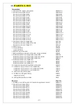
Page 47: ...annel Spacing 500KHz Frequency Control PLL Frequency Drift 2ppm 20 70 Frequency Deviation 1ppm 25 Sensitivity 110dBm Spurious Emission 50dB Antenna Impedance 50 ohms Responding Time 100ms Standard Enclosure Rating IP 66 Source Voltage α604 607 608 DC12V 24V AC48V AC380V Full voltage module AC100 240V 50 60Hz α612 DC12V 24V AC24 32 36 48V AC110V 240V AC380 460V 50 60Hz Power Consumption α604 8 Watt...

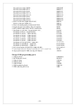
Page 48: ... cap All models EMS01 7 EMS pushbutton mechanism All models red cap included B50003 8 Pushbutton rubber boot fixing holder Alpha 604 BFH604 Pushbutton rubber boot fixing holder Alpha 607 608 BFH607 608 Pushbutton rubber boot fixing holder Alpha 612 BFH612 9 Pushbutton rubber boot Alpha 604 PRB01 Pushbutton rubber boot Alpha 607 608 PRB02 Pushbutton rubber boot Alpha 612 PRB03 10 Transmitter shock ...

Page 49: ...AC Alpha 600 608 T48VAC Transformer 110VAC Alpha 600 608 T110VAC Transformer 220VAC Alpha 600 608 T220VAC Transformer 230VAC Alpha 600 608 T230VAC Transformer 240VAC Alpha 600 608 T240VAC Transformer 380VAC Alpha 600 608 T380VAC Transformer 25 36 42 50VAC Alpha 612 T25 36 42 50VAC Transformer 110 240VAC Alpha 612 T110 240VAC Transformer 380 460VAC Alpha 612 T380 460VAC 8 Full voltage module 100 24...

Reviews: