- 12 -
18
21
20
19
17
15
5
11
12
10
8
9
7
1
3
4
2
16
13
6
14
4
4
.
.
2
2
.
.
2
2
A
A
l
l
p
p
h
h
a
a
6
6
1
1
2
2
M
M
o
o
d
d
e
e
l
l
s
s
I
I
n
n
t
t
e
e
r
r
n
n
a
a
l
l
A
A
s
s
s
s
e
e
m
m
b
b
l
l
y
y
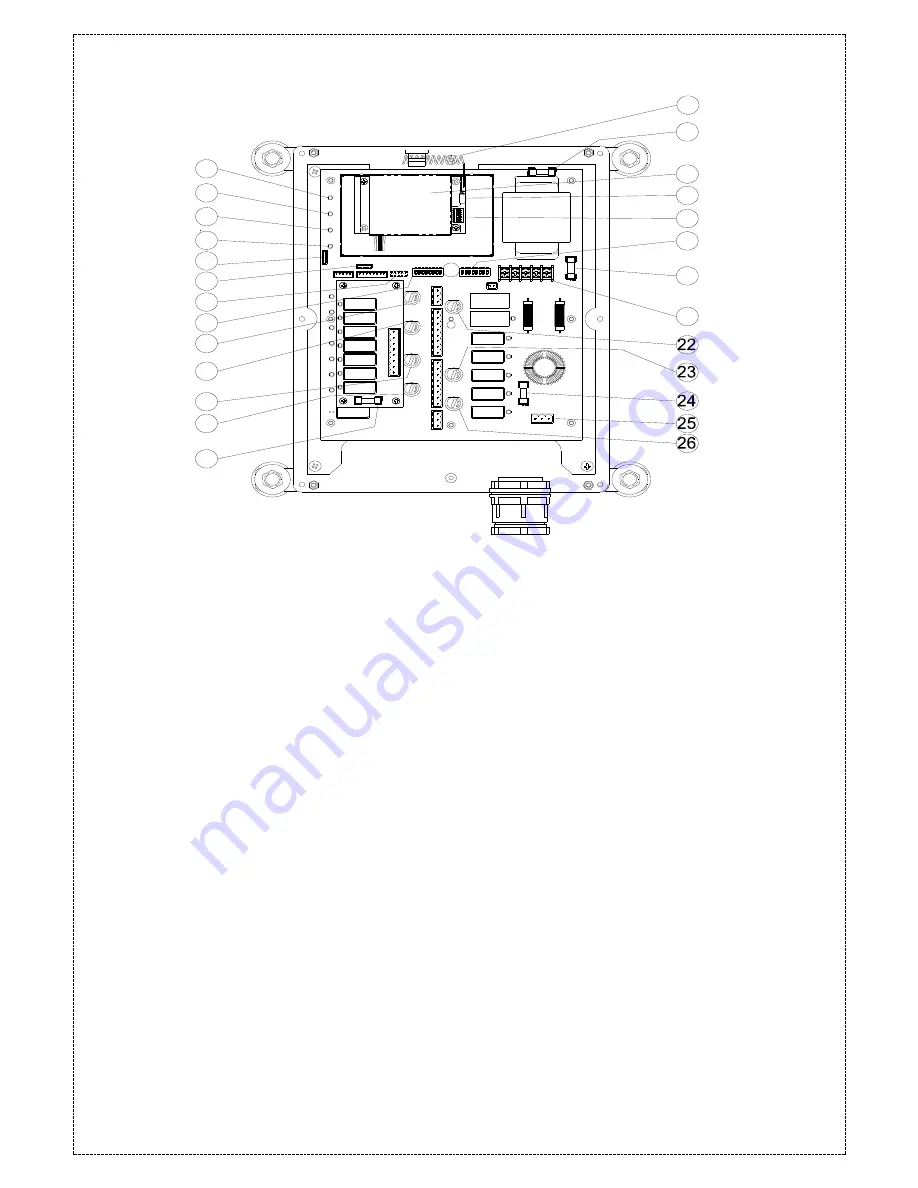
(Fig. 10) Internal Parts Assembly
1)
Power LED display*
14) Receiving antenna (see below 4.3)
2)
SQ LED display**
15) Third power fuse FF2
3)
Status LED display****
16) Receiving RF module
4)
Relay power LED display
17) External antenna port
5)
Programming port (CN3)*****
18) RF channel dip-switch
6)
Programming port (CN5)***** 19) ID code dip-switch
7)
Short pin
20) Secondary power fuse (see below 4.3)
8)
Function dip-switch
21) Voltage selector seat CN10
9)
Pushbutton #3 and #4 relay fuse F3 (5.0A) 22) MAIN relay fuse F6 (5.0A)
10) Pushbutton #5 and #6 relay fuse F3 (5.0A) 23) Pushbutton A4 relay fuse F8 (5.0A)
11) Pushbutton A1and A2 relay fuse F5 (5.0A) 24) Primary power fuse (see below 4.3)
12) Pushbutton A3 relay fuse F7 (5.0A)
25) Power port CN2
13) Pushbutton #1 and #2 relay fuse F2 (5.0A) 26) Low-voltage (LV) relay fuse F9 (5.0A)
*
POWER
~ AC Power Source Indicator "on"
→
AC input power supplied.
"off"
→
No AC input power.
**
SQ
~ RF Signal Indicator "on"
→
RF signal detected and received.
"off"
→
No RF signal detected or received.
Blinking at transmitter power “off”
→
Other radio interference.
***
RELAY_COM
~ DC Power Source to Relays "on"
→
DC power to relays.
"off"
→
No DC power to relays.
****
STATUS
~ Receiver System Status LED Display
→
Please refer to page 40.
*****
Programming port
~ Item 5 & 6, the receiver and country code / ID have to be set at the same time.


